

306
15 Goniometric Radio Navigation Systems
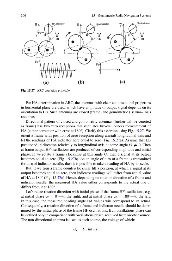
Fig. 15.27 ARC operation principle
For HA determination in ARC, the antennas with clear-cut directional properties
in horizontal plane are used, which have amplitude of output signal depends on its
orientation to LB. Such antennas are closed (frame) and goniometric (Bellini–Tosi)
antennas.
Directional pattern of closed and goniometric antennas (further will be denoted
as frame) has two zero receptions that stipulates two-valuedness measurement of
HA (either correct or with error at 180°). Clarify this assertion using Fig. 15.27. We
orient a frame with position of zero reception along aircraft longitudinal axis and
let the readings of HA indicator here equal to zero (Fig. 15.27a). Assume that LB
positioned in direction relatively to longitudinal axis at some angle = 0. Then
at frame output HF oscillations are produced of corresponding amplitude and initial
phase. If we rotate a frame clockwise at this angle , then a signal at its output
becomes equal to zero (Fig. 15.27b). As an angle of turn of a frame is transmitted
for turn of indicator needle, then it is possible to take a reading of HA by its scale.
But, if we turn a frame counterclockwise till a position, at which a signal at its
output becomes equal to zero, then indicator readings will differ from actual value
of HA at 180° (Fig. 15.27c). Hence, depending on rotation direction of a frame and
indicator needle, the measured HA value either corresponds to the actual one or
differs from it at 180°.
Let’s relate rotation direction with initial phase of the frame HF oscillations, e.g.
at initial phase ϕ 0 = 0°—to the right, and at initial phase ϕ 0 = 180°—to the left.
In this case, the measured heading angle HA values will correspond to an actual.
Consequently, a rotation direction of a frame and indicator needle should be determined by the initial phase of the frame HF oscillations. But, oscillations phase can
be defined only in comparison with oscillations phase, received from another source.
The non-directional antenna is used as such source, the voltage of which:
U v = U v sin ωt.
15 Goniometric Radio Navigation Systems
Fig. 15.27 ARC operation principle
For HA determination in ARC, the antennas with clear-cut directional properties
in horizontal plane are used, which have amplitude of output signal depends on its
orientation to LB. Such antennas are closed (frame) and goniometric (Bellini–Tosi)
antennas.
Directional pattern of closed and goniometric antennas (further will be denoted
as frame) has two zero receptions that stipulates two-valuedness measurement of
HA (either correct or with error at 180°). Clarify this assertion using Fig. 15.27. We
orient a frame with position of zero reception along aircraft longitudinal axis and
let the readings of HA indicator here equal to zero (Fig. 15.27a). Assume that LB
positioned in direction relatively to longitudinal axis at some angle = 0. Then
at frame output HF oscillations are produced of corresponding amplitude and initial
phase. If we rotate a frame clockwise at this angle , then a signal at its output
becomes equal to zero (Fig. 15.27b). As an angle of turn of a frame is transmitted
for turn of indicator needle, then it is possible to take a reading of HA by its scale.
But, if we turn a frame counterclockwise till a position, at which a signal at its
output becomes equal to zero, then indicator readings will differ from actual value
of HA at 180° (Fig. 15.27c). Hence, depending on rotation direction of a frame and
indicator needle, the measured HA value either corresponds to the actual one or
differs from it at 180°.
Let’s relate rotation direction with initial phase of the frame HF oscillations, e.g.
at initial phase ϕ 0 = 0°—to the right, and at initial phase ϕ 0 = 180°—to the left.
In this case, the measured heading angle HA values will correspond to an actual.
Consequently, a rotation direction of a frame and indicator needle should be determined by the initial phase of the frame HF oscillations. But, oscillations phase can
be defined only in comparison with oscillations phase, received from another source.
The non-directional antenna is used as such source, the voltage of which:
U v = U v sin ωt.