

15.1 Radio Beacon Goniometric Radio Navigation Systems
299
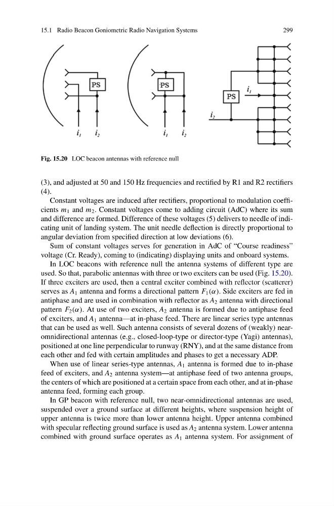
Fig. 15.20 LOC beacon antennas with reference null
(3), and adjusted at 50 and 150 Hz frequencies and rectified by R1 and R2 rectifiers
(4).
Constant voltages are induced after rectifiers, proportional to modulation coefficients m 1 and m 2 . Constant voltages come to adding circuit (AdC) where its sum
and difference are formed. Difference of these voltages (5) delivers to needle of indicating unit of landing system. The unit needle deflection is directly proportional to
angular deviation from specified direction at low deviations (6).
Sum of constant voltages serves for generation in AdC of “Course readiness”
voltage (Cr. Ready), coming to (indicating) displaying units and onboard systems.
In LOC beacons with reference null the antenna systems of different type are
used. So that, parabolic antennas with three or two exciters can be used (Fig. 15.20).
If three exciters are used, then a central exciter combined with reflector (scatterer)
serves as A 1 antenna and forms a directional pattern F 1 (α). Side exciters are fed in
antiphase and are used in combination with reflector as A 2 antenna with directional
pattern F 2 (α). At use of two exciters, A 2 antenna is formed due to antiphase feed
of exciters, and A 1 antenna—at in-phase feed. There are linear series type antennas
that can be used as well. Such antenna consists of several dozens of (weakly) nearomnidirectional antennas (e.g., closed-loop-type or director-type (Yagi) antennas),
positioned at one line perpendicular to runway (RNY), and at the same distance from
each other and fed with certain amplitudes and phases to get a necessary ADP.
When use of linear series-type antennas, A 1 antenna is formed due to in-phase
feed of exciters, and A 2 antenna system—at antiphase feed of two antenna groups,
the centers of which are positioned at a certain space from each other, and at in-phase
antenna feed, forming each group.
In GP beacon with reference null, two near-omnidirectional antennas are used,
suspended over a ground surface at different heights, where suspension height of
upper antenna is twice more than lower antenna height. Upper antenna combined
with specular reflecting ground surface is used as A 2 antenna system. Lower antenna
combined with ground surface operates as A 1 antenna system. For assignment of
299
Fig. 15.20 LOC beacon antennas with reference null
(3), and adjusted at 50 and 150 Hz frequencies and rectified by R1 and R2 rectifiers
(4).
Constant voltages are induced after rectifiers, proportional to modulation coefficients m 1 and m 2 . Constant voltages come to adding circuit (AdC) where its sum
and difference are formed. Difference of these voltages (5) delivers to needle of indicating unit of landing system. The unit needle deflection is directly proportional to
angular deviation from specified direction at low deviations (6).
Sum of constant voltages serves for generation in AdC of “Course readiness”
voltage (Cr. Ready), coming to (indicating) displaying units and onboard systems.
In LOC beacons with reference null the antenna systems of different type are
used. So that, parabolic antennas with three or two exciters can be used (Fig. 15.20).
If three exciters are used, then a central exciter combined with reflector (scatterer)
serves as A 1 antenna and forms a directional pattern F 1 (α). Side exciters are fed in
antiphase and are used in combination with reflector as A 2 antenna with directional
pattern F 2 (α). At use of two exciters, A 2 antenna is formed due to antiphase feed
of exciters, and A 1 antenna—at in-phase feed. There are linear series type antennas
that can be used as well. Such antenna consists of several dozens of (weakly) nearomnidirectional antennas (e.g., closed-loop-type or director-type (Yagi) antennas),
positioned at one line perpendicular to runway (RNY), and at the same distance from
each other and fed with certain amplitudes and phases to get a necessary ADP.
When use of linear series-type antennas, A 1 antenna is formed due to in-phase
feed of exciters, and A 2 antenna system—at antiphase feed of two antenna groups,
the centers of which are positioned at a certain space from each other, and at in-phase
antenna feed, forming each group.
In GP beacon with reference null, two near-omnidirectional antennas are used,
suspended over a ground surface at different heights, where suspension height of
upper antenna is twice more than lower antenna height. Upper antenna combined
with specular reflecting ground surface is used as A 2 antenna system. Lower antenna
combined with ground surface operates as A 1 antenna system. For assignment of