

298
15 Goniometric Radio Navigation Systems
e (t) = E M1 F 1 (α) cos ωt + E M1 F 1 (α)m 1 cos 1 t cos ωt
+ E M1 F 1 (α)m 2 cos 2 t cos ωt.
(15.32)
It is obviously that combined signal of radio beacon consists of three components:
oscillations of carrier frequency, oscillations of modulation side frequencies ω ± 1
and oscillations of modulation side frequencies ω± 2 . Amplitudes of the mentioned
components depend on aircraft position relatively to course line and are defined
correspondingly by functions F 1 (α), F 1 (α)m 1 (α) and F 1 (α)m 2 (α). In direction α =
0, the radiated oscillations (waves) of modulation side frequencies ω ± 1 and
ω ± 2 are equal. Hence, a radio beacon with reference null produces an equisignal
waves radiation of modulation side frequencies into direction of directional pattern
minimum F 1 (α). This equisignal direction serves for assignment of landing course
(heading) in LOC beacons or glide path in GP beacons.
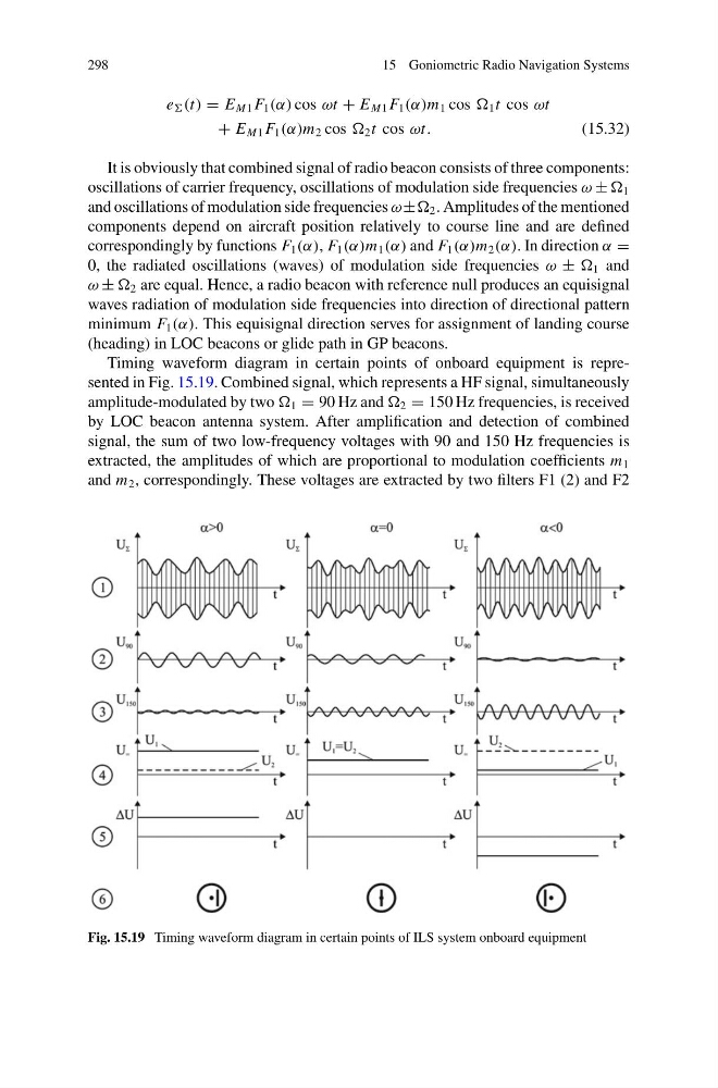
Timing waveform diagram in certain points of onboard equipment is represented in Fig. 15.19. Combined signal, which represents a HF signal, simultaneously
amplitude-modulated by two 1 = 90 Hz and 2 = 150 Hz frequencies, is received
by LOC beacon antenna system. After amplification and detection of combined
signal, the sum of two low-frequency voltages with 90 and 150 Hz frequencies is
extracted, the amplitudes of which are proportional to modulation coefficients m 1
and m 2 , correspondingly. These voltages are extracted by two filters F1 (2) and F2
Fig. 15.19 Timing waveform diagram in certain points of ILS system onboard equipment
15 Goniometric Radio Navigation Systems
e (t) = E M1 F 1 (α) cos ωt + E M1 F 1 (α)m 1 cos 1 t cos ωt
+ E M1 F 1 (α)m 2 cos 2 t cos ωt.
(15.32)
It is obviously that combined signal of radio beacon consists of three components:
oscillations of carrier frequency, oscillations of modulation side frequencies ω ± 1
and oscillations of modulation side frequencies ω± 2 . Amplitudes of the mentioned
components depend on aircraft position relatively to course line and are defined
correspondingly by functions F 1 (α), F 1 (α)m 1 (α) and F 1 (α)m 2 (α). In direction α =
0, the radiated oscillations (waves) of modulation side frequencies ω ± 1 and
ω ± 2 are equal. Hence, a radio beacon with reference null produces an equisignal
waves radiation of modulation side frequencies into direction of directional pattern
minimum F 1 (α). This equisignal direction serves for assignment of landing course
(heading) in LOC beacons or glide path in GP beacons.
Timing waveform diagram in certain points of onboard equipment is represented in Fig. 15.19. Combined signal, which represents a HF signal, simultaneously
amplitude-modulated by two 1 = 90 Hz and 2 = 150 Hz frequencies, is received
by LOC beacon antenna system. After amplification and detection of combined
signal, the sum of two low-frequency voltages with 90 and 150 Hz frequencies is
extracted, the amplitudes of which are proportional to modulation coefficients m 1
and m 2 , correspondingly. These voltages are extracted by two filters F1 (2) and F2
Fig. 15.19 Timing waveform diagram in certain points of ILS system onboard equipment