

15.1 Radio Beacon Goniometric Radio Navigation Systems
297
Z = 1 +
m +
E M2 F 2 (α)
E M1 F 1 (α)
cos 1 t +
m −
E M2 F 2 (α)
E M1 F 1 (α)
cos 2 t. (15.29)
The structure of combined field (15.29) of RB shows that it is a HF oscillation,
simultaneously amplitude-modulated by oscillations of two modulation frequencies,
the modulation coefficients of which depend on direction:
m 1 (α) = m + α
F 2 (α)
F 1 (α)
, m 2 (α) = m − α
F 2 (α)
F 1 (α)
, α =
E M2
E M1
(15.30)
Then, (15.29) can be written as:
e (t) = E M1 F 1 (α)[1 + m 1 (α) cos 1 t + m 2 (α) cos 2 t] cos ωt.
(15.31)
It is evident that structure of combined signal of equisignal radio beacon is the
same as radio beacon with reference null has. Consequently, the main properties of
these signals (shape and spectral content, changing character depending on direction
etc.) are equal, though forming ways of electromagnetic field in these beacons are
different.
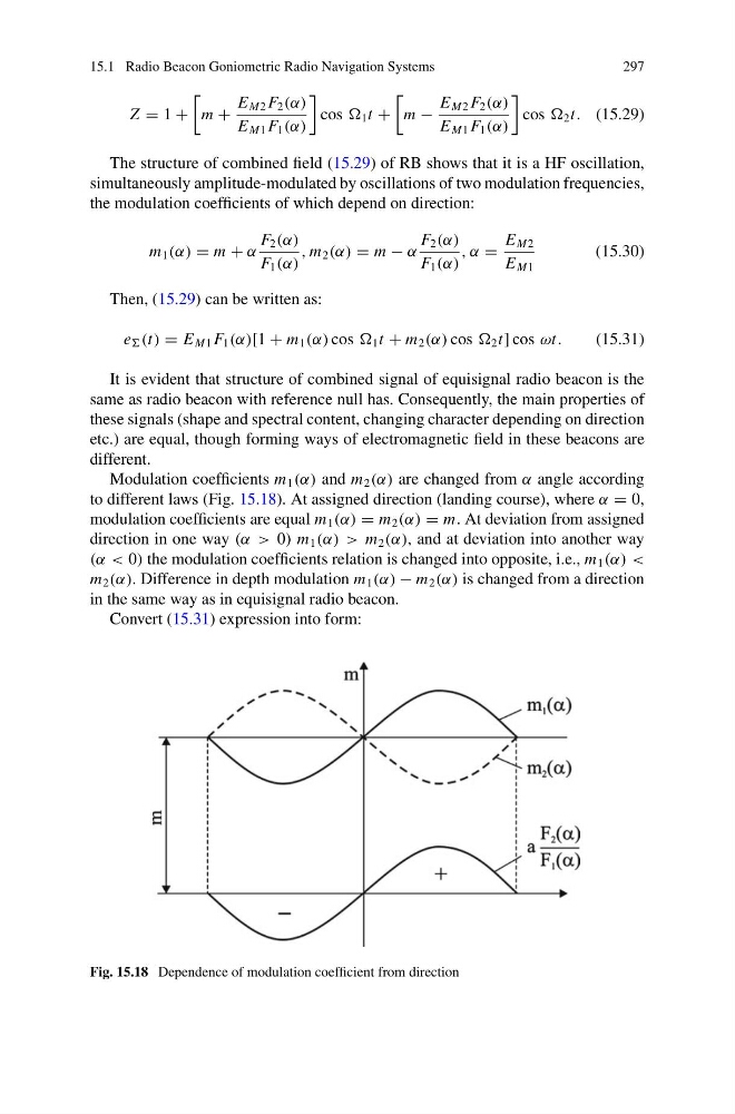
Modulation coefficients m 1 (α) and m 2 (α) are changed from α angle according
to different laws (Fig. 15.18). At assigned direction (landing course), where α = 0,
modulation coefficients are equal m 1 (α) = m 2 (α) = m. At deviation from assigned
direction in one way (α > 0) m 1 (α) > m 2 (α), and at deviation into another way
(α < 0) the modulation coefficients relation is changed into opposite, i.e., m 1 (α) <
m 2 (α). Difference in depth modulation m 1 (α) − m 2 (α) is changed from a direction
in the same way as in equisignal radio beacon.
Convert (15.31) expression into form:
Fig. 15.18 Dependence of modulation coefficient from direction
297
Z = 1 +
m +
E M2 F 2 (α)
E M1 F 1 (α)
cos 1 t +
m −
E M2 F 2 (α)
E M1 F 1 (α)
cos 2 t. (15.29)
The structure of combined field (15.29) of RB shows that it is a HF oscillation,
simultaneously amplitude-modulated by oscillations of two modulation frequencies,
the modulation coefficients of which depend on direction:
m 1 (α) = m + α
F 2 (α)
F 1 (α)
, m 2 (α) = m − α
F 2 (α)
F 1 (α)
, α =
E M2
E M1
(15.30)
Then, (15.29) can be written as:
e (t) = E M1 F 1 (α)[1 + m 1 (α) cos 1 t + m 2 (α) cos 2 t] cos ωt.
(15.31)
It is evident that structure of combined signal of equisignal radio beacon is the
same as radio beacon with reference null has. Consequently, the main properties of
these signals (shape and spectral content, changing character depending on direction
etc.) are equal, though forming ways of electromagnetic field in these beacons are
different.
Modulation coefficients m 1 (α) and m 2 (α) are changed from α angle according
to different laws (Fig. 15.18). At assigned direction (landing course), where α = 0,
modulation coefficients are equal m 1 (α) = m 2 (α) = m. At deviation from assigned
direction in one way (α > 0) m 1 (α) > m 2 (α), and at deviation into another way
(α < 0) the modulation coefficients relation is changed into opposite, i.e., m 1 (α) <
m 2 (α). Difference in depth modulation m 1 (α) − m 2 (α) is changed from a direction
in the same way as in equisignal radio beacon.
Convert (15.31) expression into form:
Fig. 15.18 Dependence of modulation coefficient from direction