

296
15 Goniometric Radio Navigation Systems
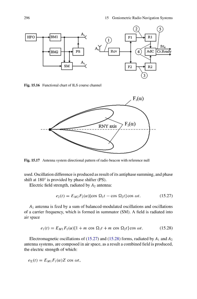
Fig. 15.16 Functional chart of ILS course channel
Fig. 15.17 Antenna system directional pattern of radio beacon with reference null
used. Oscillation difference is produced as result of its antiphase summing, and phase
shift at 180° is provided by phase shifter (PS).
Electric field strength, radiated by A 2 antenna:
e 2 (t) = E M2 F 2 (α)[cos 1 t − cos 2 t] cos ωt.
(15.27)
A 1 antenna is feed by a sum of balanced-modulated oscillations and oscillations
of a carrier frequency, which is formed in summator (SM). A field is radiated into
air space
e 1 (t) = E M1 F 1 (α)[1 + m cos 1 t + m cos 2 t] cos ωt.
(15.28)
Electromagnetic oscillations of (15.27) and (15.28) forms, radiated by A 1 and A 2
antenna systems, are composed in air space, as a result a combined field is produced,
the electric strength of which:
e (t) = E M1 F 1 (α)Z cos ωt,
15 Goniometric Radio Navigation Systems
Fig. 15.16 Functional chart of ILS course channel
Fig. 15.17 Antenna system directional pattern of radio beacon with reference null
used. Oscillation difference is produced as result of its antiphase summing, and phase
shift at 180° is provided by phase shifter (PS).
Electric field strength, radiated by A 2 antenna:
e 2 (t) = E M2 F 2 (α)[cos 1 t − cos 2 t] cos ωt.
(15.27)
A 1 antenna is feed by a sum of balanced-modulated oscillations and oscillations
of a carrier frequency, which is formed in summator (SM). A field is radiated into
air space
e 1 (t) = E M1 F 1 (α)[1 + m cos 1 t + m cos 2 t] cos ωt.
(15.28)
Electromagnetic oscillations of (15.27) and (15.28) forms, radiated by A 1 and A 2
antenna systems, are composed in air space, as a result a combined field is produced,
the electric strength of which:
e (t) = E M1 F 1 (α)Z cos ωt,