

15.1 Radio Beacon Goniometric Radio Navigation Systems
295
From (15.26) expressions, it is followed that in that direction where F 1 (α) =
F 2 (α), modulation coefficients for 1 and 2 frequencies are equal. Hence, a radio
beacon produces an equisignal radiation of modulation side frequencies in direction of directional patterns intersection F 1 (α) and F 2 (α) of beacon antennas. This
equisignal direction serves for assignment of landing flight path (trajectory). At
deviation from equisignal direction the modulation coefficients are changed.
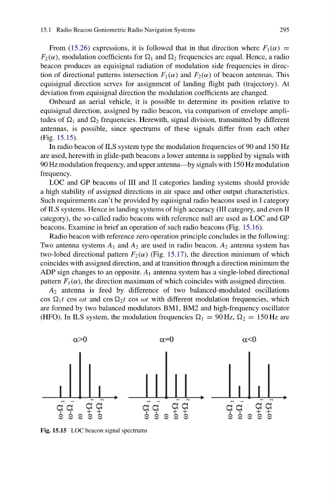
Onboard an aerial vehicle, it is possible to determine its position relative to
equisignal direction, assigned by radio beacon, via comparison of envelope amplitudes of 1 and 2 frequencies. Herewith, signal division, transmitted by different
antennas, is possible, since spectrums of these signals differ from each other
(Fig. 15.15).
In radio beacon of ILS system type the modulation frequencies of 90 and 150 Hz
are used, herewith in glide-path beacons a lower antenna is supplied by signals with
90 Hz modulation frequency, and upper antenna—by signals with 150 Hz modulation
frequency.
LOC and GP beacons of III and II categories landing systems should provide
a high stability of assigned directions in air space and other output characteristics.
Such requirements can’t be provided by equisignal radio beacons used in I category
of ILS systems. Hence in landing systems of high accuracy (III category, and even II
category), the so-called radio beacons with reference null are used as LOC and GP
beacons. Examine in brief an operation of such radio beacons (Fig. 15.16).
Radio beacon with reference zero operation principle concludes in the following:
Two antenna systems A 1 and A 2 are used in radio beacon. A 2 antenna system has
two-lobed directional pattern F 2 (α) (Fig. 15.17), the direction minimum of which
coincides with assigned direction, and at transition through a direction minimum the
ADP sign changes to an opposite. A 1 antenna system has a single-lobed directional
pattern F 1 (α), the direction maximum of which coincides with assigned direction.
A 2 antenna is feed by difference of two balanced-modulated oscillations
cos 1 t cos ωt and cos 2 t cos ωt with different modulation frequencies, which
are formed by two balanced modulators BM1, BM2 and high-frequency oscillator
(HFO). In ILS system, the modulation frequencies 1 = 90 Hz, 2 = 150 Hz are
Fig. 15.15 LOC beacon signal spectrums
295
From (15.26) expressions, it is followed that in that direction where F 1 (α) =
F 2 (α), modulation coefficients for 1 and 2 frequencies are equal. Hence, a radio
beacon produces an equisignal radiation of modulation side frequencies in direction of directional patterns intersection F 1 (α) and F 2 (α) of beacon antennas. This
equisignal direction serves for assignment of landing flight path (trajectory). At
deviation from equisignal direction the modulation coefficients are changed.
Onboard an aerial vehicle, it is possible to determine its position relative to
equisignal direction, assigned by radio beacon, via comparison of envelope amplitudes of 1 and 2 frequencies. Herewith, signal division, transmitted by different
antennas, is possible, since spectrums of these signals differ from each other
(Fig. 15.15).
In radio beacon of ILS system type the modulation frequencies of 90 and 150 Hz
are used, herewith in glide-path beacons a lower antenna is supplied by signals with
90 Hz modulation frequency, and upper antenna—by signals with 150 Hz modulation
frequency.
LOC and GP beacons of III and II categories landing systems should provide
a high stability of assigned directions in air space and other output characteristics.
Such requirements can’t be provided by equisignal radio beacons used in I category
of ILS systems. Hence in landing systems of high accuracy (III category, and even II
category), the so-called radio beacons with reference null are used as LOC and GP
beacons. Examine in brief an operation of such radio beacons (Fig. 15.16).
Radio beacon with reference zero operation principle concludes in the following:
Two antenna systems A 1 and A 2 are used in radio beacon. A 2 antenna system has
two-lobed directional pattern F 2 (α) (Fig. 15.17), the direction minimum of which
coincides with assigned direction, and at transition through a direction minimum the
ADP sign changes to an opposite. A 1 antenna system has a single-lobed directional
pattern F 1 (α), the direction maximum of which coincides with assigned direction.
A 2 antenna is feed by difference of two balanced-modulated oscillations
cos 1 t cos ωt and cos 2 t cos ωt with different modulation frequencies, which
are formed by two balanced modulators BM1, BM2 and high-frequency oscillator
(HFO). In ILS system, the modulation frequencies 1 = 90 Hz, 2 = 150 Hz are
Fig. 15.15 LOC beacon signal spectrums