

294
15 Goniometric Radio Navigation Systems
relative to assigned direction can be judged by relation of modulation coefficients,
i.e., via envelope amplitudes comparison of two modulation frequencies.
Localizer beacon antennas have combined electrical centers, and currents,
supplying these antennas are in phase, and therefore in air space, surrounding a
radio beacon, two in-phase fields are formed.
In air space, electromagnetic fields, excited by each antenna, are composed and
as a result a combined field is produced, an expression for strength of which has the
following form:
e (t) = E M F 3 (α)
1 +
F 1 (α)
F 3 (α)
m cos 1 t +
F 2 (α)
F 3 (α)
m cos 2 t
cos ωt, (15.25)
or
e (t) = E M F 3 (α)[1 + m 1 (α) cos 1 t + m 2 (α) cos 2 t] cos ωt,
where F 3 (α) = F 1 (α) + F 2 (α); E M —amplitude in peak of directional pattern;
m 1 (α)—modulation coefficient for frequency 1 ; m 2 (α)—modulation coefficient
for frequency 2 .
Expression (15.25) shows that combined field of a beacon is simultaneously modulated by two 1 and 2 frequencies. It formed from three components: combined
field of carrier frequency ω and two fields of side frequencies of modulation ω ± 1
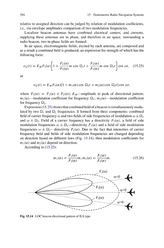
and ω ± 2 . Field of a carrier frequency has a directivity F 3 (α), a field of side
modulation frequencies ω ± 1 —directivity F 1 (α) and a field of side modulation
frequencies ω ± 2 —directivity F 2 (α). Due to the fact that intensities of carrier
frequency field and fields of side modulation frequencies are changed depending
on direction based on different laws (Fig. 15.14), then modulation coefficients for
m 1 (α) and m 2 (α) depend on direction.
According to (15.25):
m 1 (α) =
F 1 (α)
F 3 (α)
m, m 1 (α) =
F 2 (α)
F 3 (α)
m.
(15.26)
Fig. 15.14 LOC beacon directional pattern of ILS type
15 Goniometric Radio Navigation Systems
relative to assigned direction can be judged by relation of modulation coefficients,
i.e., via envelope amplitudes comparison of two modulation frequencies.
Localizer beacon antennas have combined electrical centers, and currents,
supplying these antennas are in phase, and therefore in air space, surrounding a
radio beacon, two in-phase fields are formed.
In air space, electromagnetic fields, excited by each antenna, are composed and
as a result a combined field is produced, an expression for strength of which has the
following form:
e (t) = E M F 3 (α)
1 +
F 1 (α)
F 3 (α)
m cos 1 t +
F 2 (α)
F 3 (α)
m cos 2 t
cos ωt, (15.25)
or
e (t) = E M F 3 (α)[1 + m 1 (α) cos 1 t + m 2 (α) cos 2 t] cos ωt,
where F 3 (α) = F 1 (α) + F 2 (α); E M —amplitude in peak of directional pattern;
m 1 (α)—modulation coefficient for frequency 1 ; m 2 (α)—modulation coefficient
for frequency 2 .
Expression (15.25) shows that combined field of a beacon is simultaneously modulated by two 1 and 2 frequencies. It formed from three components: combined
field of carrier frequency ω and two fields of side frequencies of modulation ω ± 1
and ω ± 2 . Field of a carrier frequency has a directivity F 3 (α), a field of side
modulation frequencies ω ± 1 —directivity F 1 (α) and a field of side modulation
frequencies ω ± 2 —directivity F 2 (α). Due to the fact that intensities of carrier
frequency field and fields of side modulation frequencies are changed depending
on direction based on different laws (Fig. 15.14), then modulation coefficients for
m 1 (α) and m 2 (α) depend on direction.
According to (15.25):
m 1 (α) =
F 1 (α)
F 3 (α)
m, m 1 (α) =
F 2 (α)
F 3 (α)
m.
(15.26)
Fig. 15.14 LOC beacon directional pattern of ILS type