

15.1 Radio Beacon Goniometric Radio Navigation Systems
293
Table 15.1 VOR radio beacon specifications
No. RB type
DME-90
VOR-734
DVOR 2000
1
Bandwidth, MHz
108…118
108…118
108…118
2
Coverage zone in HP: deg.
0…360
0…360
0…360
km
300
300
300
3
Coverage zone in VP, deg.
0…40
–
0…40
4
Azimuth measuring error, deg.
±1
–
±0.2
5
Operational environment: temperature, °C −50…+50 −50…+70 −50…+50
Wind load, m/s
50
55
50
Precipitations, mm/min
–
–
up to 3
It is almost managed to exclude an influence of terrain features on azimuth channel
accuracy at development of Precision Doppler VOR (PDVOR). In ground radio
beacons of this system, a signal of reference phase is transmitted via frequency
modulation of auxiliary subcarrier frequency of 6500 Hz. The advantages of PDVOR
system can be realized only by using special onboard equipment. Standard VOR
receiver operates with PDVOR radio beacons in the same way as with DVOR radio
beacons. For this purpose, the components in PDVOR signal spectrum are remained,
corresponding to DVOR reference signal.
Table 15.1 states specifications of modern VOR RB.
Localizer (azimuth transmitter) beacon (LOC) and glide-path (elevation transmitter) beacon (GP) of instrument landing systems type are referred to goniometric
RNS of radio beacon type. They have the same principle of operation and are functioning as equisignal beacons. Regarding this, the system operating principle will be
examined at an example of localizers of ILS landing system.
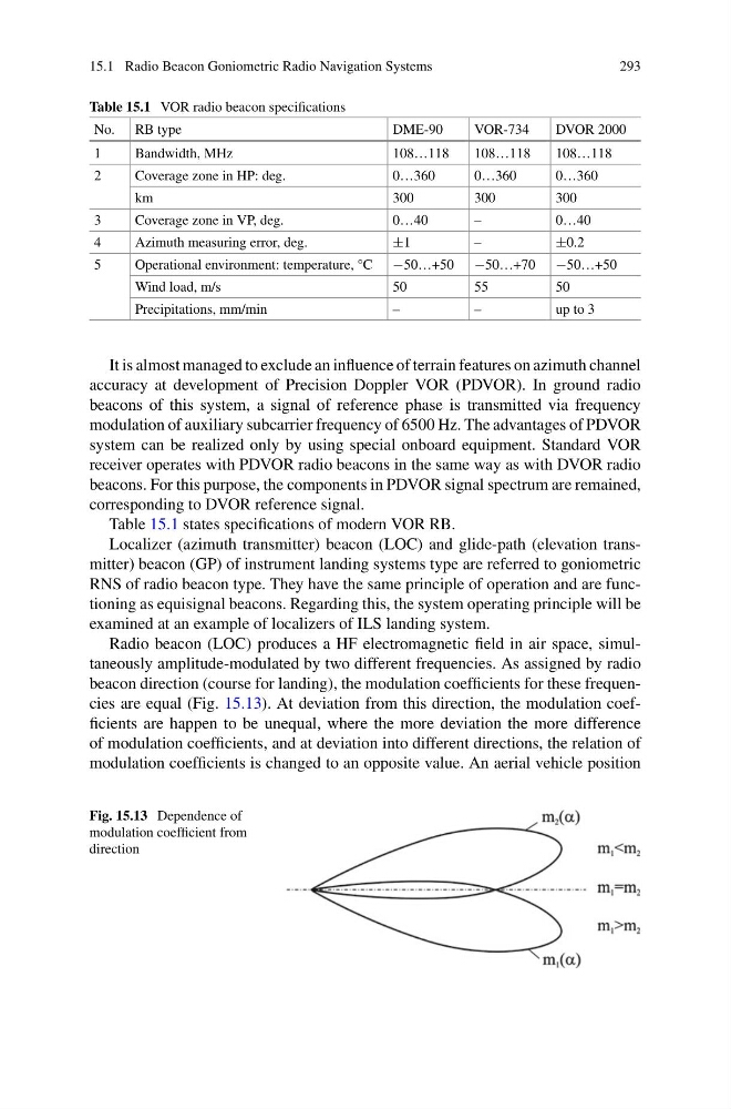
Radio beacon (LOC) produces a HF electromagnetic field in air space, simultaneously amplitude-modulated by two different frequencies. As assigned by radio
beacon direction (course for landing), the modulation coefficients for these frequencies are equal (Fig. 15.13). At deviation from this direction, the modulation coefficients are happen to be unequal, where the more deviation the more difference
of modulation coefficients, and at deviation into different directions, the relation of
modulation coefficients is changed to an opposite value. An aerial vehicle position
Fig. 15.13 Dependence of
modulation coefficient from
direction
293
Table 15.1 VOR radio beacon specifications
No. RB type
DME-90
VOR-734
DVOR 2000
1
Bandwidth, MHz
108…118
108…118
108…118
2
Coverage zone in HP: deg.
0…360
0…360
0…360
km
300
300
300
3
Coverage zone in VP, deg.
0…40
–
0…40
4
Azimuth measuring error, deg.
±1
–
±0.2
5
Operational environment: temperature, °C −50…+50 −50…+70 −50…+50
Wind load, m/s
50
55
50
Precipitations, mm/min
–
–
up to 3
It is almost managed to exclude an influence of terrain features on azimuth channel
accuracy at development of Precision Doppler VOR (PDVOR). In ground radio
beacons of this system, a signal of reference phase is transmitted via frequency
modulation of auxiliary subcarrier frequency of 6500 Hz. The advantages of PDVOR
system can be realized only by using special onboard equipment. Standard VOR
receiver operates with PDVOR radio beacons in the same way as with DVOR radio
beacons. For this purpose, the components in PDVOR signal spectrum are remained,
corresponding to DVOR reference signal.
Table 15.1 states specifications of modern VOR RB.
Localizer (azimuth transmitter) beacon (LOC) and glide-path (elevation transmitter) beacon (GP) of instrument landing systems type are referred to goniometric
RNS of radio beacon type. They have the same principle of operation and are functioning as equisignal beacons. Regarding this, the system operating principle will be
examined at an example of localizers of ILS landing system.
Radio beacon (LOC) produces a HF electromagnetic field in air space, simultaneously amplitude-modulated by two different frequencies. As assigned by radio
beacon direction (course for landing), the modulation coefficients for these frequencies are equal (Fig. 15.13). At deviation from this direction, the modulation coefficients are happen to be unequal, where the more deviation the more difference
of modulation coefficients, and at deviation into different directions, the relation of
modulation coefficients is changed to an opposite value. An aerial vehicle position
Fig. 15.13 Dependence of
modulation coefficient from
direction