

292
15 Goniometric Radio Navigation Systems
Reference signal is radiated through the central antenna, representing an
amplitude-modulated oscillations:
e cnt (t) = E cntM (1 + m ref cos t) cos ω 0 t.
A signal is generated at receiving point as a result of fields summing of central
antenna and side dipoles:
e (t) = E cntM Z cos ω 0 t,
Z = 1 + m ref cos t + m subc cos( subc t + m FM cos((t − θ)),
(15.24)
where m FM =
2π R
λ
—frequency modulation index.
From (15.24) expression, we can see that this signal in its structure is identical to
signal of standard VOR. The difference of signal processing of DVOR radio beacon
consists in that azimuthal signal (variable phase signal) is transmitted via FM channel
and extracted by F2 filter, and reference signal is transmitted via AM channel and is
extracted in onboard equipment by F1 filter.
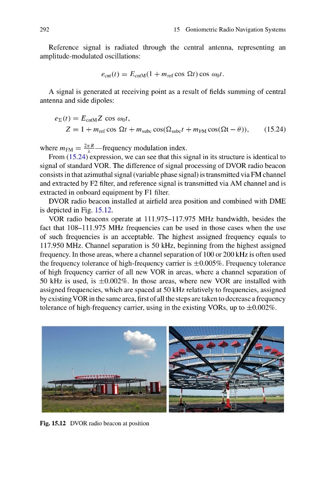
DVOR radio beacon installed at airfield area position and combined with DME
is depicted in Fig. 15.12.
VOR radio beacons operate at 111.975–117.975 MHz bandwidth, besides the
fact that 108–111.975 MHz frequencies can be used in those cases when the use
of such frequencies is an acceptable. The highest assigned frequency equals to
117.950 MHz. Channel separation is 50 kHz, beginning from the highest assigned
frequency. In those areas, where a channel separation of 100 or 200 kHz is often used
the frequency tolerance of high-frequency carrier is ±0.005%. Frequency tolerance
of high frequency carrier of all new VOR in areas, where a channel separation of
50 kHz is used, is ±0.002%. In those areas, where new VOR are installed with
assigned frequencies, which are spaced at 50 kHz relatively to frequencies, assigned
by existing VOR in the same area, first of all the steps are taken to decrease a frequency
tolerance of high-frequency carrier, using in the existing VORs, up to ±0.002%.
Fig. 15.12 DVOR radio beacon at position
15 Goniometric Radio Navigation Systems
Reference signal is radiated through the central antenna, representing an
amplitude-modulated oscillations:
e cnt (t) = E cntM (1 + m ref cos t) cos ω 0 t.
A signal is generated at receiving point as a result of fields summing of central
antenna and side dipoles:
e (t) = E cntM Z cos ω 0 t,
Z = 1 + m ref cos t + m subc cos( subc t + m FM cos((t − θ)),
(15.24)
where m FM =
2π R
λ
—frequency modulation index.
From (15.24) expression, we can see that this signal in its structure is identical to
signal of standard VOR. The difference of signal processing of DVOR radio beacon
consists in that azimuthal signal (variable phase signal) is transmitted via FM channel
and extracted by F2 filter, and reference signal is transmitted via AM channel and is
extracted in onboard equipment by F1 filter.
DVOR radio beacon installed at airfield area position and combined with DME
is depicted in Fig. 15.12.
VOR radio beacons operate at 111.975–117.975 MHz bandwidth, besides the
fact that 108–111.975 MHz frequencies can be used in those cases when the use
of such frequencies is an acceptable. The highest assigned frequency equals to
117.950 MHz. Channel separation is 50 kHz, beginning from the highest assigned
frequency. In those areas, where a channel separation of 100 or 200 kHz is often used
the frequency tolerance of high-frequency carrier is ±0.005%. Frequency tolerance
of high frequency carrier of all new VOR in areas, where a channel separation of
50 kHz is used, is ±0.002%. In those areas, where new VOR are installed with
assigned frequencies, which are spaced at 50 kHz relatively to frequencies, assigned
by existing VOR in the same area, first of all the steps are taken to decrease a frequency
tolerance of high-frequency carrier, using in the existing VORs, up to ±0.002%.
Fig. 15.12 DVOR radio beacon at position