

15.1 Radio Beacon Goniometric Radio Navigation Systems
291
The reference voltage of the form u ref (t) = U refM cos t comes onboard AV
through the central antenna A cnt , the phase of which does not depend on azimuth.
By comparing of reference and variable signals phase, an AV azimuth is determined
in onboard equipment.
The main advantage of Doppler VOR RB comparing with standard VOR RB—
is a high suppression efficiency of clutter influence on operation accuracy. For an
effective suppression, the antennas’ rotation radius R should be relatively large and
comprises
2R
λ
= 4 . . . 6, and direction finding rate should be maintained high that
demands a high rotation rate. For this reason, instead of rotating antennas the fixed
antenna arrays are installed in modern DVOR systems, comprising a large amount of
circularly positioned antennas, and electronic commutation (switching) of antennas
is used. Herewith, signal formats of Doppler VOR radio beacons are to be selected as
equal with VOR RB in order to have a possibility of its receiving using a single-type
onboard equipment without any upgrading or replacement.
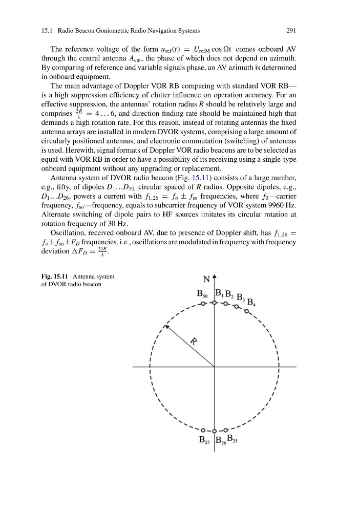
Antenna system of DVOR radio beacon (Fig. 15.11) consists of a large number,
e.g., fifty, of dipoles D 1 …D 50, circular spaced of R radius. Opposite dipoles, e.g.,
D 1 …D 26 , powers a current with f 1,26 = f o ± f so frequencies, where f 0 —carrier
frequency, f so —frequency, equals to subcarrier frequency of VOR system 9960 Hz.
Alternate switching of dipole pairs to HF sources imitates its circular rotation at
rotation frequency of 30 Hz.
Oscillation, received onboard AV, due to presence of Doppler shift, has f 1,26 =
f o ± f so ±F D frequencies, i.e., oscillations are modulated in frequency with frequency
deviation F D =
R
λ
.
Fig. 15.11 Antenna system
of DVOR radio beacon
291
The reference voltage of the form u ref (t) = U refM cos t comes onboard AV
through the central antenna A cnt , the phase of which does not depend on azimuth.
By comparing of reference and variable signals phase, an AV azimuth is determined
in onboard equipment.
The main advantage of Doppler VOR RB comparing with standard VOR RB—
is a high suppression efficiency of clutter influence on operation accuracy. For an
effective suppression, the antennas’ rotation radius R should be relatively large and
comprises
2R
λ
= 4 . . . 6, and direction finding rate should be maintained high that
demands a high rotation rate. For this reason, instead of rotating antennas the fixed
antenna arrays are installed in modern DVOR systems, comprising a large amount of
circularly positioned antennas, and electronic commutation (switching) of antennas
is used. Herewith, signal formats of Doppler VOR radio beacons are to be selected as
equal with VOR RB in order to have a possibility of its receiving using a single-type
onboard equipment without any upgrading or replacement.
Antenna system of DVOR radio beacon (Fig. 15.11) consists of a large number,
e.g., fifty, of dipoles D 1 …D 50, circular spaced of R radius. Opposite dipoles, e.g.,
D 1 …D 26 , powers a current with f 1,26 = f o ± f so frequencies, where f 0 —carrier
frequency, f so —frequency, equals to subcarrier frequency of VOR system 9960 Hz.
Alternate switching of dipole pairs to HF sources imitates its circular rotation at
rotation frequency of 30 Hz.
Oscillation, received onboard AV, due to presence of Doppler shift, has f 1,26 =
f o ± f so ±F D frequencies, i.e., oscillations are modulated in frequency with frequency
deviation F D =
R
λ
.
Fig. 15.11 Antenna system
of DVOR radio beacon