

15.1 Radio Beacon Goniometric Radio Navigation Systems
285
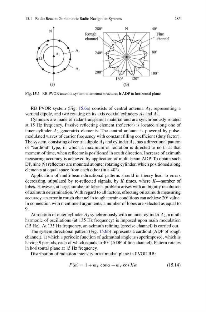
Fig. 15.6 RB PVOR antenna system: a antenna structure; b ADP in horizontal plane
RB PVOR system (Fig. 15.6a) consists of central antenna A 1 , representing a
vertical dipole, and two rotating on its axis coaxial cylinders A 2 and A 3 .
Cylinders are made of radar-transparent material and are synchronously rotated
at 15 Hz frequency. Passive reflecting element (reflector) is located along one of
inner cylinder A 2 generatrix elements. The central antenna is powered by pulsemodulated waves of carrier frequency with constant filling coefficient (duty factor).
The system, consisting of central dipole A 1 and cylinder A 2 , has a directional pattern
of “cardioid” type, in which a maximum of radiation is directed to north at that
moment of time, when reflector is positioned in south direction. Increase of azimuth
measuring accuracy is achieved by application of multi-beam ADP. To obtain such
DP, nine (9) reflectors are mounted at outer rotating cylinder, which positioned along
elements at equal space from each other (in a 40°).
Application of multi-beam directional patterns should in theory lead to errors
decreasing, stipulated by re-reflected signals, by K times, where K—number of
lobes. However, at large number of lobes a problem arises with ambiguity resolution
of azimuth determination. With regard to all factors, effecting on azimuth measuring
accuracy, an error in rough channel in tough terrain conditions can achieve 20° value.
In connection with mentioned arguments, a number of lobes are selected as equal to
9.
At rotation of outer cylinder A 3 synchronously with an inner cylinder A 2 , a ninth
harmonic of oscillations (at 135 Hz frequency) is imposed upon main modulation
(15 Hz). At 135 Hz frequency, an azimuth refining (precise channel) is carried out.
The system directional pattern (Fig. 15.6b) represents a cardioid (ADP of rough
channel), at which a periodic function of azimuthal angle is superimposed, which is
having 9 periods, each of which equals to 40° (ADP of fine channel). Pattern rotates
in horizontal plane at 15 Hz frequency.
Distribution of radiation intensity in azimuthal plane in PVOR RB:
F(α) = 1 + m D cos α + m T cos K α
(15.14)
285
Fig. 15.6 RB PVOR antenna system: a antenna structure; b ADP in horizontal plane
RB PVOR system (Fig. 15.6a) consists of central antenna A 1 , representing a
vertical dipole, and two rotating on its axis coaxial cylinders A 2 and A 3 .
Cylinders are made of radar-transparent material and are synchronously rotated
at 15 Hz frequency. Passive reflecting element (reflector) is located along one of
inner cylinder A 2 generatrix elements. The central antenna is powered by pulsemodulated waves of carrier frequency with constant filling coefficient (duty factor).
The system, consisting of central dipole A 1 and cylinder A 2 , has a directional pattern
of “cardioid” type, in which a maximum of radiation is directed to north at that
moment of time, when reflector is positioned in south direction. Increase of azimuth
measuring accuracy is achieved by application of multi-beam ADP. To obtain such
DP, nine (9) reflectors are mounted at outer rotating cylinder, which positioned along
elements at equal space from each other (in a 40°).
Application of multi-beam directional patterns should in theory lead to errors
decreasing, stipulated by re-reflected signals, by K times, where K—number of
lobes. However, at large number of lobes a problem arises with ambiguity resolution
of azimuth determination. With regard to all factors, effecting on azimuth measuring
accuracy, an error in rough channel in tough terrain conditions can achieve 20° value.
In connection with mentioned arguments, a number of lobes are selected as equal to
9.
At rotation of outer cylinder A 3 synchronously with an inner cylinder A 2 , a ninth
harmonic of oscillations (at 135 Hz frequency) is imposed upon main modulation
(15 Hz). At 135 Hz frequency, an azimuth refining (precise channel) is carried out.
The system directional pattern (Fig. 15.6b) represents a cardioid (ADP of rough
channel), at which a periodic function of azimuthal angle is superimposed, which is
having 9 periods, each of which equals to 40° (ADP of fine channel). Pattern rotates
in horizontal plane at 15 Hz frequency.
Distribution of radiation intensity in azimuthal plane in PVOR RB:
F(α) = 1 + m D cos α + m T cos K α
(15.14)