

286
15 Goniometric Radio Navigation Systems
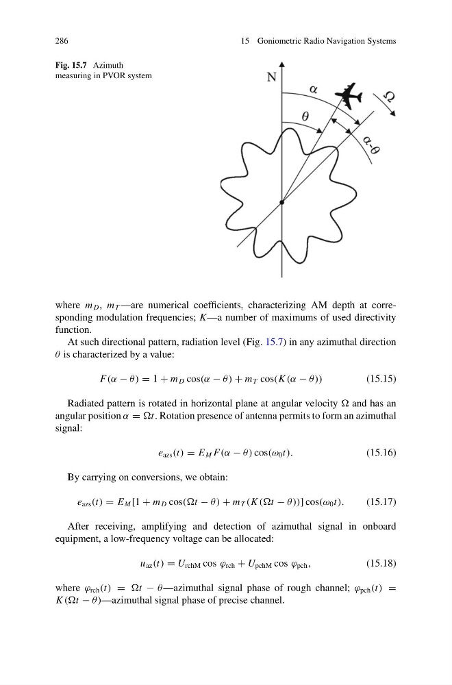
Fig. 15.7 Azimuth
measuring in PVOR system
where m D , m T —are numerical coefficients, characterizing AM depth at corresponding modulation frequencies; K—a number of maximums of used directivity
function.
At such directional pattern, radiation level (Fig. 15.7) in any azimuthal direction
θ is characterized by a value:
F(α − θ ) = 1 + m D cos(α − θ ) + m T cos(K (α − θ ))
(15.15)
Radiated pattern is rotated in horizontal plane at angular velocity and has an
angular position α = t. Rotation presence of antenna permits to form an azimuthal
signal:
e azs (t) = E M F(α − θ ) cos(ω 0 t).
(15.16)
By carrying on conversions, we obtain:
e azs (t) = E M [1 + m D cos(t − θ ) + m T (K (t − θ))] cos(ω 0 t).
(15.17)
After receiving, amplifying and detection of azimuthal signal in onboard
equipment, a low-frequency voltage can be allocated:
u az (t) = U rchM cos ϕ rch + U pchM cos ϕ pch ,
(15.18)
where ϕ rch (t) = t − θ —azimuthal signal phase of rough channel; ϕ pch (t) =
K (t − θ )—azimuthal signal phase of precise channel.
15 Goniometric Radio Navigation Systems
Fig. 15.7 Azimuth
measuring in PVOR system
where m D , m T —are numerical coefficients, characterizing AM depth at corresponding modulation frequencies; K—a number of maximums of used directivity
function.
At such directional pattern, radiation level (Fig. 15.7) in any azimuthal direction
θ is characterized by a value:
F(α − θ ) = 1 + m D cos(α − θ ) + m T cos(K (α − θ ))
(15.15)
Radiated pattern is rotated in horizontal plane at angular velocity and has an
angular position α = t. Rotation presence of antenna permits to form an azimuthal
signal:
e azs (t) = E M F(α − θ ) cos(ω 0 t).
(15.16)
By carrying on conversions, we obtain:
e azs (t) = E M [1 + m D cos(t − θ ) + m T (K (t − θ))] cos(ω 0 t).
(15.17)
After receiving, amplifying and detection of azimuthal signal in onboard
equipment, a low-frequency voltage can be allocated:
u az (t) = U rchM cos ϕ rch + U pchM cos ϕ pch ,
(15.18)
where ϕ rch (t) = t − θ —azimuthal signal phase of rough channel; ϕ pch (t) =
K (t − θ )—azimuthal signal phase of precise channel.