

15.1 Radio Beacon Goniometric Radio Navigation Systems
283
This voltage delivers to PD2 input. Azimuthal voltage (pattern) u az is delivered
to the second input with phase ϕ az (t) = t − θ . Phases difference of azimuthal and
reference voltages at PD2 input ϕ = θ − θ sp . After phase detection at detector
output—U pd (t) = U max sin θ . When U pd = 0, θ = θ sp AV azimuth coincides
with specified direction. This problem is solved at AV flight to direction to VOR
radio beacon or from it. For indicating flight towards a radio beacon or backward,
the FD3 is introduced into a circuit, to which:
• azimuthal voltage U az (t) = U 2M cos(t − θ );
• reference voltage U ref (t) = U refM cos
cos t − θ sp + 90
◦
are applied.
Phase difference of these voltages ϕ = θ − θ sp + 90
◦ . At flight on VOR
RB, when θ = θ sp , at PD3 output U pd = +U max . “TO” placard on crew indicator
corresponds to positive voltage presence. At RB flight, the current AV azimuth is
changed at 180°, then θ = θ sp ± 180
◦ . Azimuth change induces a voltage polarity
change at PD3 output U pd = −U max , herewith, “FROM” placard is indicated.
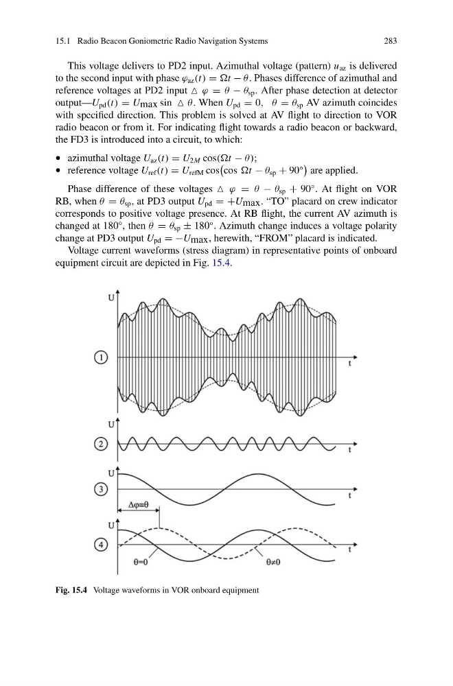
Voltage current waveforms (stress diagram) in representative points of onboard
equipment circuit are depicted in Fig. 15.4.
Fig. 15.4 Voltage waveforms in VOR onboard equipment
283
This voltage delivers to PD2 input. Azimuthal voltage (pattern) u az is delivered
to the second input with phase ϕ az (t) = t − θ . Phases difference of azimuthal and
reference voltages at PD2 input ϕ = θ − θ sp . After phase detection at detector
output—U pd (t) = U max sin θ . When U pd = 0, θ = θ sp AV azimuth coincides
with specified direction. This problem is solved at AV flight to direction to VOR
radio beacon or from it. For indicating flight towards a radio beacon or backward,
the FD3 is introduced into a circuit, to which:
• azimuthal voltage U az (t) = U 2M cos(t − θ );
• reference voltage U ref (t) = U refM cos
cos t − θ sp + 90
◦
are applied.
Phase difference of these voltages ϕ = θ − θ sp + 90
◦ . At flight on VOR
RB, when θ = θ sp , at PD3 output U pd = +U max . “TO” placard on crew indicator
corresponds to positive voltage presence. At RB flight, the current AV azimuth is
changed at 180°, then θ = θ sp ± 180
◦ . Azimuth change induces a voltage polarity
change at PD3 output U pd = −U max , herewith, “FROM” placard is indicated.
Voltage current waveforms (stress diagram) in representative points of onboard
equipment circuit are depicted in Fig. 15.4.
Fig. 15.4 Voltage waveforms in VOR onboard equipment