

282
15 Goniometric Radio Navigation Systems
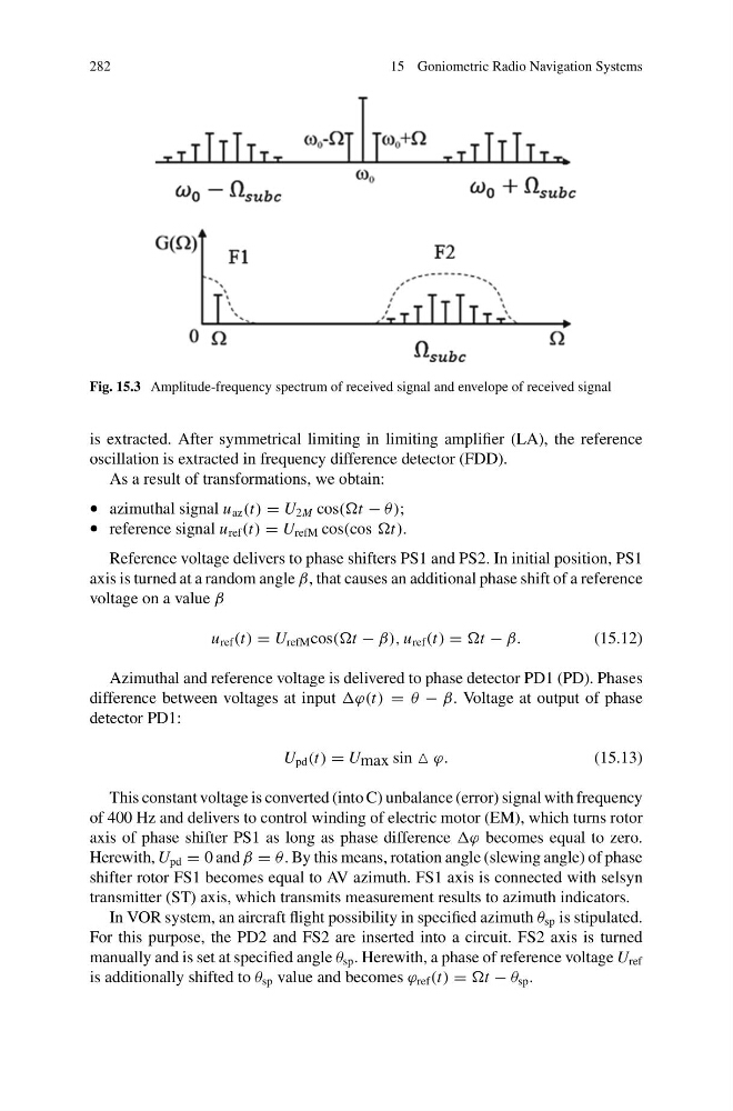
Fig. 15.3 Amplitude-frequency spectrum of received signal and envelope of received signal
is extracted. After symmetrical limiting in limiting amplifier (LA), the reference
oscillation is extracted in frequency difference detector (FDD).
As a result of transformations, we obtain:
• azimuthal signal u az (t) = U 2M cos(t − θ );
• reference signal u ref (t) = U refM cos(cos t).
Reference voltage delivers to phase shifters PS1 and PS2. In initial position, PS1
axis is turned at a random angle β, that causes an additional phase shift of a reference
voltage on a value β
u ref (t) = U refM cos(t − β), u ref (t) = t − β.
(15.12)
Azimuthal and reference voltage is delivered to phase detector PD1 (PD). Phases
difference between voltages at input ϕ(t) = θ − β. Voltage at output of phase
detector PD1:
U pd (t) = U max sin ϕ.
(15.13)
This constant voltage is converted (into C) unbalance (error) signal with frequency
of 400 Hz and delivers to control winding of electric motor (EM), which turns rotor
axis of phase shifter PS1 as long as phase difference ϕ becomes equal to zero.
Herewith, U pd = 0 and β = θ . By this means, rotation angle (slewing angle) of phase
shifter rotor FS1 becomes equal to AV azimuth. FS1 axis is connected with selsyn
transmitter (ST) axis, which transmits measurement results to azimuth indicators.
In VOR system, an aircraft flight possibility in specified azimuth θ sp is stipulated.
For this purpose, the PD2 and FS2 are inserted into a circuit. FS2 axis is turned
manually and is set at specified angle θ sp . Herewith, a phase of reference voltage U ref
is additionally shifted to θ sp value and becomes ϕ ref (t) = t − θ sp .
15 Goniometric Radio Navigation Systems
Fig. 15.3 Amplitude-frequency spectrum of received signal and envelope of received signal
is extracted. After symmetrical limiting in limiting amplifier (LA), the reference
oscillation is extracted in frequency difference detector (FDD).
As a result of transformations, we obtain:
• azimuthal signal u az (t) = U 2M cos(t − θ );
• reference signal u ref (t) = U refM cos(cos t).
Reference voltage delivers to phase shifters PS1 and PS2. In initial position, PS1
axis is turned at a random angle β, that causes an additional phase shift of a reference
voltage on a value β
u ref (t) = U refM cos(t − β), u ref (t) = t − β.
(15.12)
Azimuthal and reference voltage is delivered to phase detector PD1 (PD). Phases
difference between voltages at input ϕ(t) = θ − β. Voltage at output of phase
detector PD1:
U pd (t) = U max sin ϕ.
(15.13)
This constant voltage is converted (into C) unbalance (error) signal with frequency
of 400 Hz and delivers to control winding of electric motor (EM), which turns rotor
axis of phase shifter PS1 as long as phase difference ϕ becomes equal to zero.
Herewith, U pd = 0 and β = θ . By this means, rotation angle (slewing angle) of phase
shifter rotor FS1 becomes equal to AV azimuth. FS1 axis is connected with selsyn
transmitter (ST) axis, which transmits measurement results to azimuth indicators.
In VOR system, an aircraft flight possibility in specified azimuth θ sp is stipulated.
For this purpose, the PD2 and FS2 are inserted into a circuit. FS2 axis is turned
manually and is set at specified angle θ sp . Herewith, a phase of reference voltage U ref
is additionally shifted to θ sp value and becomes ϕ ref (t) = t − θ sp .