

224
12 Radar Systems of Maritime Transport
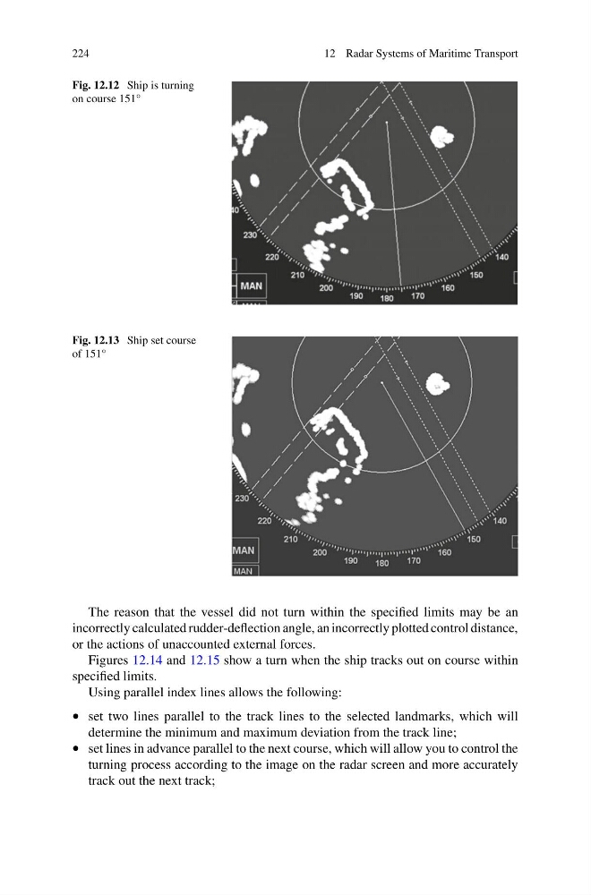
Fig. 12.12 Ship is turning
on course 151°
Fig. 12.13 Ship set course
of 151°
The reason that the vessel did not turn within the specified limits may be an
incorrectly calculated rudder-deflection angle, an incorrectly plotted control distance,
or the actions of unaccounted external forces.
Figures 12.14 and 12.15 show a turn when the ship tracks out on course within
specified limits.
Using parallel index lines allows the following:
• set two lines parallel to the track lines to the selected landmarks, which will
determine the minimum and maximum deviation from the track line;
• set lines in advance parallel to the next course, which will allow you to control the
turning process according to the image on the radar screen and more accurately
track out the next track;
12 Radar Systems of Maritime Transport
Fig. 12.12 Ship is turning
on course 151°
Fig. 12.13 Ship set course
of 151°
The reason that the vessel did not turn within the specified limits may be an
incorrectly calculated rudder-deflection angle, an incorrectly plotted control distance,
or the actions of unaccounted external forces.
Figures 12.14 and 12.15 show a turn when the ship tracks out on course within
specified limits.
Using parallel index lines allows the following:
• set two lines parallel to the track lines to the selected landmarks, which will
determine the minimum and maximum deviation from the track line;
• set lines in advance parallel to the next course, which will allow you to control the
turning process according to the image on the radar screen and more accurately
track out the next track;