

11 Radar Systems of Air Transport
199
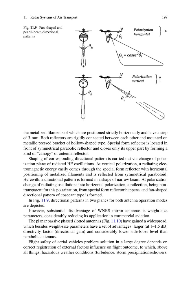
Fig. 11.9 Fan-shaped and
pencil-beam directional
patterns
the metalized filaments of which are positioned strictly horizontally and have a step
of 3-mm. Both reflectors are rigidly connected between each other and mounted on
metallic pressed bracket of hollow-shaped type. Special form reflector is located in
front of symmetrical parabolic reflector and closes only its upper part by forming a
kind of “canopy” of antenna reflector.
Shaping of corresponding directional pattern is carried out via change of polarization plane of radiated HF oscillations. At vertical polarization, a radiating electromagnetic energy easily comes through the special form reflector with horizontal
positioning of metalized filaments and is reflected from symmetrical paraboloid.
Herewith, a directional pattern is formed in a shape of narrow beam. At polarization
change of radiating oscillations into horizontal polarization, a reflection, being nontransparent for this polarization, from special form reflector happens, and fan-shaped
directional pattern of cosecant type is formed.
In Fig. 11.9, directional patterns in two planes for both antenna operation modes
are depicted.
However, substantial disadvantage of WNRS mirror antennas is weight-size
parameters, considerably reducing its application in commercial aviation.
The planar passive phased slotted antennas (Fig. 11.10) have gained a widespread,
which besides weight-size parameters have a set of advantages: larger (at 1–1.5 dB)
directivity factor (directional gain) and considerably lower side-lobes level than
parabolic antennas.
Flight safety of aerial vehicles problem solution in a large degree depends on
correct registration of external factors influence on flight outcome, to which, above
all things, hazardous weather conditions (turbulence, storm precipitations/showers,
199
Fig. 11.9 Fan-shaped and
pencil-beam directional
patterns
the metalized filaments of which are positioned strictly horizontally and have a step
of 3-mm. Both reflectors are rigidly connected between each other and mounted on
metallic pressed bracket of hollow-shaped type. Special form reflector is located in
front of symmetrical parabolic reflector and closes only its upper part by forming a
kind of “canopy” of antenna reflector.
Shaping of corresponding directional pattern is carried out via change of polarization plane of radiated HF oscillations. At vertical polarization, a radiating electromagnetic energy easily comes through the special form reflector with horizontal
positioning of metalized filaments and is reflected from symmetrical paraboloid.
Herewith, a directional pattern is formed in a shape of narrow beam. At polarization
change of radiating oscillations into horizontal polarization, a reflection, being nontransparent for this polarization, from special form reflector happens, and fan-shaped
directional pattern of cosecant type is formed.
In Fig. 11.9, directional patterns in two planes for both antenna operation modes
are depicted.
However, substantial disadvantage of WNRS mirror antennas is weight-size
parameters, considerably reducing its application in commercial aviation.
The planar passive phased slotted antennas (Fig. 11.10) have gained a widespread,
which besides weight-size parameters have a set of advantages: larger (at 1–1.5 dB)
directivity factor (directional gain) and considerably lower side-lobes level than
parabolic antennas.
Flight safety of aerial vehicles problem solution in a large degree depends on
correct registration of external factors influence on flight outcome, to which, above
all things, hazardous weather conditions (turbulence, storm precipitations/showers,