

188
10 Multi-channel Radar Systems
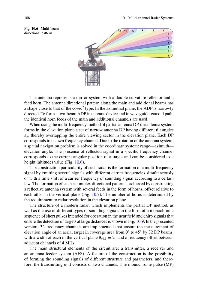
Fig. 10.6 Multi-beam
directional pattern
The antenna represents a mirror system with a double curvature reflector and a
feed horn. The antenna directional pattern along the main and additional beams has
a shape close to that of the cosec
2 type. In the azimuthal plane, the ADP is narrowly
directed. To form a two-beam ADP in antenna device and in waveguide-coaxial path,
the identical horn feeds of the main and additional channels are used.
When using the multi-frequency method of partial antenna DP, the antenna system
forms in the elevation plane a set of narrow antenna DP having different tilt angles
ε n , thereby overlapping the entire viewing sector in the elevation plane. Each DP
corresponds to its own frequency channel. Due to the rotation of the antenna system,
a spatial navigation problem is solved in the coordinate system: range—azimuth—
elevation angle. The presence of reflected signal in a specific frequency channel
corresponds to the current angular position of a target and can be considered as a
height (altitude) value (Fig. 10.6).
The construction particularity of such radar is the formation of a multi-frequency
signal by emitting several signals with different carrier frequencies simultaneously
or with a time shift of a carrier frequency of sounding signal according to a certain
law. The formation of such a complex directional pattern is achieved by constructing
a reflective antenna system with several feeds in the form of horns, offset relative to
each other in the vertical plane (Fig. 10.7). The number of horns is determined by
the requirement to radar resolution in the elevation plane.
The structure of a modern radar, which implements the partial DP method, as
well as the use of different types of sounding signals in the form of a monochrome
sequence of short pulses intended for operation in the near field and chirp signals that
ensure the detection of targets at large distances is shown in Fig. 10.9. In the presented
version, 32 frequency channels are implemented that ensure the measurement of
elevation angle of an aerial target in coverage area from 0° to 45° by 32 DP beams,
with a width of each in the vertical plane θ v0.5 = 2° and a frequency offset between
adjacent channels of 4 MHz.
The main structural elements of the circuit are: a transmitter, a receiver and
an antenna-feeder system (AFS). A feature of the construction is the possibility
of forming the sounding signals of different structure and parameters, and therefore, the transmitting unit consists of two channels. The monochrome pulse (MP)
10 Multi-channel Radar Systems
Fig. 10.6 Multi-beam
directional pattern
The antenna represents a mirror system with a double curvature reflector and a
feed horn. The antenna directional pattern along the main and additional beams has
a shape close to that of the cosec
2 type. In the azimuthal plane, the ADP is narrowly
directed. To form a two-beam ADP in antenna device and in waveguide-coaxial path,
the identical horn feeds of the main and additional channels are used.
When using the multi-frequency method of partial antenna DP, the antenna system
forms in the elevation plane a set of narrow antenna DP having different tilt angles
ε n , thereby overlapping the entire viewing sector in the elevation plane. Each DP
corresponds to its own frequency channel. Due to the rotation of the antenna system,
a spatial navigation problem is solved in the coordinate system: range—azimuth—
elevation angle. The presence of reflected signal in a specific frequency channel
corresponds to the current angular position of a target and can be considered as a
height (altitude) value (Fig. 10.6).
The construction particularity of such radar is the formation of a multi-frequency
signal by emitting several signals with different carrier frequencies simultaneously
or with a time shift of a carrier frequency of sounding signal according to a certain
law. The formation of such a complex directional pattern is achieved by constructing
a reflective antenna system with several feeds in the form of horns, offset relative to
each other in the vertical plane (Fig. 10.7). The number of horns is determined by
the requirement to radar resolution in the elevation plane.
The structure of a modern radar, which implements the partial DP method, as
well as the use of different types of sounding signals in the form of a monochrome
sequence of short pulses intended for operation in the near field and chirp signals that
ensure the detection of targets at large distances is shown in Fig. 10.9. In the presented
version, 32 frequency channels are implemented that ensure the measurement of
elevation angle of an aerial target in coverage area from 0° to 45° by 32 DP beams,
with a width of each in the vertical plane θ v0.5 = 2° and a frequency offset between
adjacent channels of 4 MHz.
The main structural elements of the circuit are: a transmitter, a receiver and
an antenna-feeder system (AFS). A feature of the construction is the possibility
of forming the sounding signals of different structure and parameters, and therefore, the transmitting unit consists of two channels. The monochrome pulse (MP)