

10 Multi-channel Radar Systems
189
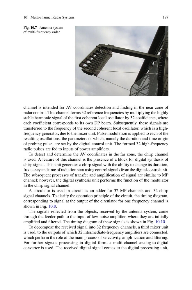
Fig. 10.7 Antenna system
of multi-frequency radar
channel is intended for AV coordinates detection and finding in the near zone of
radar control. This channel forms 32 reference frequencies by multiplying the highly
stable harmonic signal of the first coherent local oscillator by 32 coefficients, where
each coefficient corresponds to its own DP beam. Subsequently, these signals are
transferred to the frequency of the second coherent local oscillator, which is a highfrequency generator, due to the mixer unit. Pulse modulation is applied to each of the
resulting oscillations, the parameters of which, namely the duration and time origin
of probing pulse, are set by the digital control unit. The formed 32 high-frequency
radio pulses are fed to inputs of power amplifiers.
To detect and determine the AV coordinates in the far zone, the chirp channel
is used. A feature of this channel is the presence of a block for digital synthesis of
chirp signal. This unit generates a chirp signal with the ability to change its duration,
frequency and time of radiation start using control signals from the digital control unit.
The subsequent processes of transfer and amplification of signal are similar to MP
channel; however, the digital synthesis unit performs the function of the modulator
in the chirp signal channel.
A circulator is used in circuit as an adder for 32 MP channels and 32 chirp
signal channels. To clarify the operation principle of the circuit, the timing diagram,
corresponding to signal at the output of the circulator for one frequency channel is
shown in Fig. 10.8.
The signals reflected from the objects, received by the antenna system, come
through the feeder path to the input of low-noise amplifier, where they are initially
amplified and filtered. The timing diagram of these signals is shown in Fig. 10.10.
To decompose the received signal into 32 frequency channels, a third mixer unit
is used, to the outputs of which 32 intermediate-frequency amplifiers are connected,
which perform the role of the main process of selectivity, amplification and filtering.
For further signals processing in digital form, a multi-channel analog-to-digital
converter is used. The received digital signal comes to the digital processing unit,
189
Fig. 10.7 Antenna system
of multi-frequency radar
channel is intended for AV coordinates detection and finding in the near zone of
radar control. This channel forms 32 reference frequencies by multiplying the highly
stable harmonic signal of the first coherent local oscillator by 32 coefficients, where
each coefficient corresponds to its own DP beam. Subsequently, these signals are
transferred to the frequency of the second coherent local oscillator, which is a highfrequency generator, due to the mixer unit. Pulse modulation is applied to each of the
resulting oscillations, the parameters of which, namely the duration and time origin
of probing pulse, are set by the digital control unit. The formed 32 high-frequency
radio pulses are fed to inputs of power amplifiers.
To detect and determine the AV coordinates in the far zone, the chirp channel
is used. A feature of this channel is the presence of a block for digital synthesis of
chirp signal. This unit generates a chirp signal with the ability to change its duration,
frequency and time of radiation start using control signals from the digital control unit.
The subsequent processes of transfer and amplification of signal are similar to MP
channel; however, the digital synthesis unit performs the function of the modulator
in the chirp signal channel.
A circulator is used in circuit as an adder for 32 MP channels and 32 chirp
signal channels. To clarify the operation principle of the circuit, the timing diagram,
corresponding to signal at the output of the circulator for one frequency channel is
shown in Fig. 10.8.
The signals reflected from the objects, received by the antenna system, come
through the feeder path to the input of low-noise amplifier, where they are initially
amplified and filtered. The timing diagram of these signals is shown in Fig. 10.10.
To decompose the received signal into 32 frequency channels, a third mixer unit
is used, to the outputs of which 32 intermediate-frequency amplifiers are connected,
which perform the role of the main process of selectivity, amplification and filtering.
For further signals processing in digital form, a multi-channel analog-to-digital
converter is used. The received digital signal comes to the digital processing unit,