

10 Multi-channel Radar Systems
183
coordinates using a single reflected pulse, but increasing the range and accuracy of
coordinate readings is possible only by using the energy of many pulses.
Information processing in monopulse radars consists in comparing the amplitudes
and phases of the reflected signal during its simultaneous reception in spaced-apart
channels. In particular, four receiving channels are required for automatic angle track
on target in two perpendicular planes.
In onboard devices, usually four emitters (e.g., horns) are used, placed with a slight
shift near the focus of the common reflector. The dimensions of the antenna system
are changed insignificantly, although instead of a single-channel one, a four-channel
reception and radar information processing is provided.
Low-frequency amplitude fluctuations of reflected signal, occurring due to fluctuations in the effective scattering area of a target or due to arising of interference, do not
influence on the measurement of angular coordinates by monopulse radars. Therefore, they are distinguished by significantly higher noise immunity and accuracy of
angular tracking of a target.
There are many types of monopulse radars that differ in the way they process
signals, received by several channels. The simplest type of monopulse radar is an
amplitude-difference radar, in which in order to determine the direction to a target,
the amplitudes of signals, received by different channels, are compared (Fig. 10.2).
Suppose that at the moment the misalignment angle (error angle) between the
direction to a target and the equal-signal direction of the antenna is γ. After
frequency conversion, intermediate-frequency amplification and detecting, we obtain
the following voltages at the output of the first and the second channels, that is, at
two inputs of the subtraction circuit:
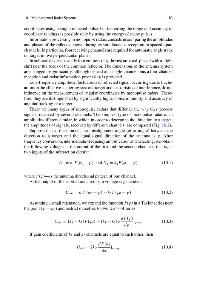
U 1 = k 1 F(ϕ 0 + γ ), and U 2 = k 2 F(ϕ 0 − γ )
(10.1)
where F(ϕ)—is the antenna directional pattern of one channel.
At the output of the subtraction circuits, a voltage is generated:
U out = k 1 F(ϕ 0 + γ ) − k 2 F(ϕ 0 − γ )
(10.2)
Assuming a small mismatch, we expand the function F(ϕ) in a Taylor series near
the point (ϕ = ϕ 0 ) and restrict ourselves to two terms of series:
U out = (k 1 − k 2 )F(ϕ 0 ) + (k 1 + k 2 )γ
d F(ϕ)
dϕ
| ϕ=ϕ 0
(10.3)
If gain coefficients of k 1 and k 2 channels are equal to each other, then
U out = 2kγ
d F(ϕ)
dϕ
| ϕ=ϕ 0
(10.4)
183
coordinates using a single reflected pulse, but increasing the range and accuracy of
coordinate readings is possible only by using the energy of many pulses.
Information processing in monopulse radars consists in comparing the amplitudes
and phases of the reflected signal during its simultaneous reception in spaced-apart
channels. In particular, four receiving channels are required for automatic angle track
on target in two perpendicular planes.
In onboard devices, usually four emitters (e.g., horns) are used, placed with a slight
shift near the focus of the common reflector. The dimensions of the antenna system
are changed insignificantly, although instead of a single-channel one, a four-channel
reception and radar information processing is provided.
Low-frequency amplitude fluctuations of reflected signal, occurring due to fluctuations in the effective scattering area of a target or due to arising of interference, do not
influence on the measurement of angular coordinates by monopulse radars. Therefore, they are distinguished by significantly higher noise immunity and accuracy of
angular tracking of a target.
There are many types of monopulse radars that differ in the way they process
signals, received by several channels. The simplest type of monopulse radar is an
amplitude-difference radar, in which in order to determine the direction to a target,
the amplitudes of signals, received by different channels, are compared (Fig. 10.2).
Suppose that at the moment the misalignment angle (error angle) between the
direction to a target and the equal-signal direction of the antenna is γ. After
frequency conversion, intermediate-frequency amplification and detecting, we obtain
the following voltages at the output of the first and the second channels, that is, at
two inputs of the subtraction circuit:
U 1 = k 1 F(ϕ 0 + γ ), and U 2 = k 2 F(ϕ 0 − γ )
(10.1)
where F(ϕ)—is the antenna directional pattern of one channel.
At the output of the subtraction circuits, a voltage is generated:
U out = k 1 F(ϕ 0 + γ ) − k 2 F(ϕ 0 − γ )
(10.2)
Assuming a small mismatch, we expand the function F(ϕ) in a Taylor series near
the point (ϕ = ϕ 0 ) and restrict ourselves to two terms of series:
U out = (k 1 − k 2 )F(ϕ 0 ) + (k 1 + k 2 )γ
d F(ϕ)
dϕ
| ϕ=ϕ 0
(10.3)
If gain coefficients of k 1 and k 2 channels are equal to each other, then
U out = 2kγ
d F(ϕ)
dϕ
| ϕ=ϕ 0
(10.4)