

184
10 Multi-channel Radar Systems
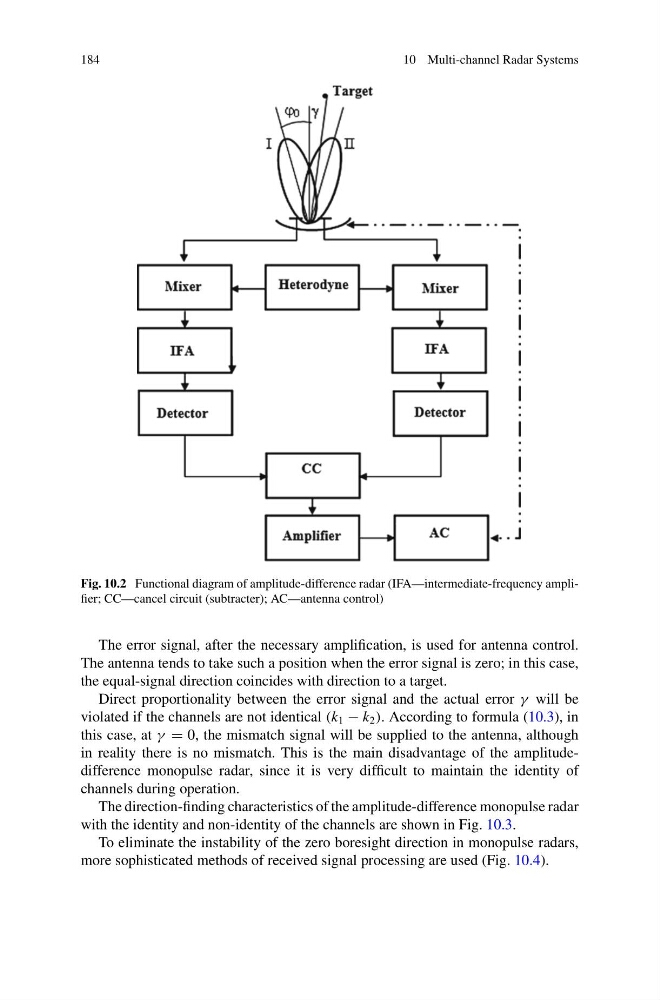
Fig. 10.2 Functional diagram of amplitude-difference radar (IFA—intermediate-frequency amplifier; CC—cancel circuit (subtracter); AC—antenna control)
The error signal, after the necessary amplification, is used for antenna control.
The antenna tends to take such a position when the error signal is zero; in this case,
the equal-signal direction coincides with direction to a target.
Direct proportionality between the error signal and the actual error γ will be
violated if the channels are not identical (k 1 − k 2 ). According to formula (10.3), in
this case, at γ = 0, the mismatch signal will be supplied to the antenna, although
in reality there is no mismatch. This is the main disadvantage of the amplitudedifference monopulse radar, since it is very difficult to maintain the identity of
channels during operation.
The direction-finding characteristics of the amplitude-difference monopulse radar
with the identity and non-identity of the channels are shown in Fig. 10.3.
To eliminate the instability of the zero boresight direction in monopulse radars,
more sophisticated methods of received signal processing are used (Fig. 10.4).
10 Multi-channel Radar Systems
Fig. 10.2 Functional diagram of amplitude-difference radar (IFA—intermediate-frequency amplifier; CC—cancel circuit (subtracter); AC—antenna control)
The error signal, after the necessary amplification, is used for antenna control.
The antenna tends to take such a position when the error signal is zero; in this case,
the equal-signal direction coincides with direction to a target.
Direct proportionality between the error signal and the actual error γ will be
violated if the channels are not identical (k 1 − k 2 ). According to formula (10.3), in
this case, at γ = 0, the mismatch signal will be supplied to the antenna, although
in reality there is no mismatch. This is the main disadvantage of the amplitudedifference monopulse radar, since it is very difficult to maintain the identity of
channels during operation.
The direction-finding characteristics of the amplitude-difference monopulse radar
with the identity and non-identity of the channels are shown in Fig. 10.3.
To eliminate the instability of the zero boresight direction in monopulse radars,
more sophisticated methods of received signal processing are used (Fig. 10.4).