

5.3 Operating Space of Radar Location and Radio Navigation Systems
105
Almost all in-service present bearing and distance RNS operate in VHF band, and
hence, a calculation of D max should be carried out with respect to object altitude and
terrain features between object and ground-based station.
At plotting of equal accuracy curves, considering that σ l1 = Dσ θ , σ l2 = σ D and
α M =
π
2
, according to (5.49), we obtain:
σ r =
(Dσ θ )
2
+ σ
2
D .
(5.63)
Based on expression (5.63), giving σ r = σ r dr , a curve of equal accuracy of bearing
and distance measuring system can be defined:
R tr =
σ
2
r dr − σ
2
D
σ θ
= const,
(5.64)
which represents a circle of radius R tr . A center of this circle coincides with a position
of ground-based station.
Outer boundary of operating zone of bearing and distance measuring RNS
(BDRNS) is formed after curves were plotting on a map, corresponding to D max
and R tr , as a boundary total areas part, surrounding by these curves. Inner boundary
of operating zone is defined by a radius of non-operating zone around a ground-based
station, stipulated by its technical characteristics (e.g., by directional patterns).
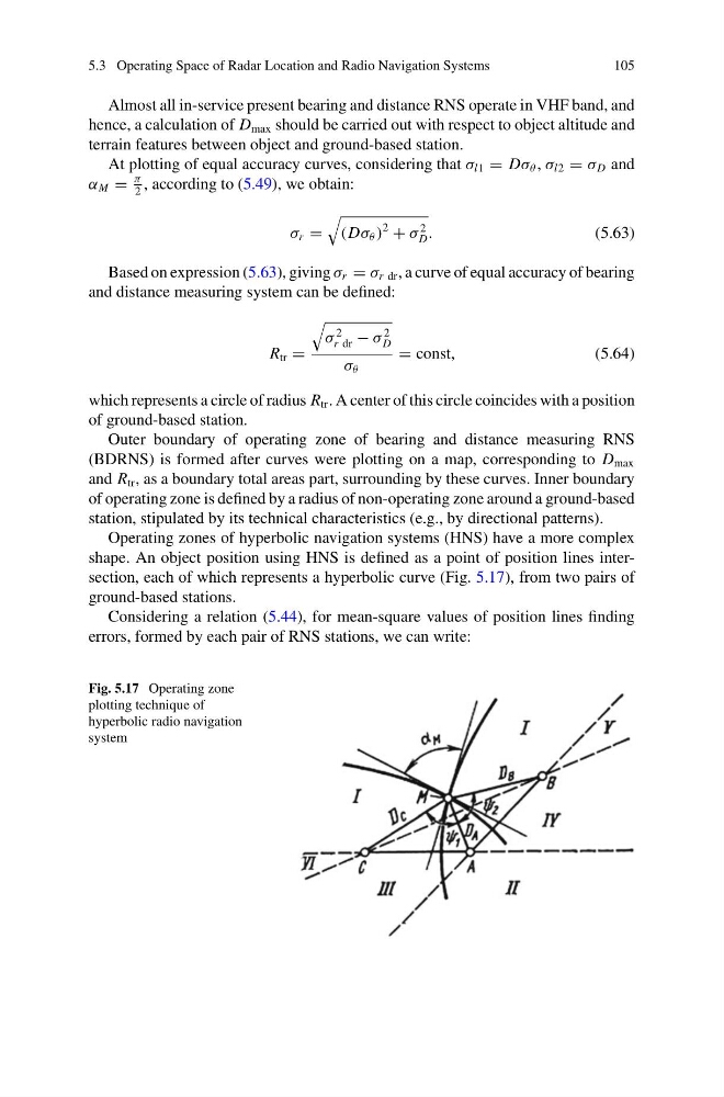
Operating zones of hyperbolic navigation systems (HNS) have a more complex
shape. An object position using HNS is defined as a point of position lines intersection, each of which represents a hyperbolic curve (Fig. 5.17), from two pairs of
ground-based stations.
Considering a relation (5.44), for mean-square values of position lines finding
errors, formed by each pair of RNS stations, we can write:
Fig. 5.17 Operating zone
plotting technique of
hyperbolic radio navigation
system
105
Almost all in-service present bearing and distance RNS operate in VHF band, and
hence, a calculation of D max should be carried out with respect to object altitude and
terrain features between object and ground-based station.
At plotting of equal accuracy curves, considering that σ l1 = Dσ θ , σ l2 = σ D and
α M =
π
2
, according to (5.49), we obtain:
σ r =
(Dσ θ )
2
+ σ
2
D .
(5.63)
Based on expression (5.63), giving σ r = σ r dr , a curve of equal accuracy of bearing
and distance measuring system can be defined:
R tr =
σ
2
r dr − σ
2
D
σ θ
= const,
(5.64)
which represents a circle of radius R tr . A center of this circle coincides with a position
of ground-based station.
Outer boundary of operating zone of bearing and distance measuring RNS
(BDRNS) is formed after curves were plotting on a map, corresponding to D max
and R tr , as a boundary total areas part, surrounding by these curves. Inner boundary
of operating zone is defined by a radius of non-operating zone around a ground-based
station, stipulated by its technical characteristics (e.g., by directional patterns).
Operating zones of hyperbolic navigation systems (HNS) have a more complex
shape. An object position using HNS is defined as a point of position lines intersection, each of which represents a hyperbolic curve (Fig. 5.17), from two pairs of
ground-based stations.
Considering a relation (5.44), for mean-square values of position lines finding
errors, formed by each pair of RNS stations, we can write:
Fig. 5.17 Operating zone
plotting technique of
hyperbolic radio navigation
system