

5.3 Operating Space of Radar Location and Radio Navigation Systems
103
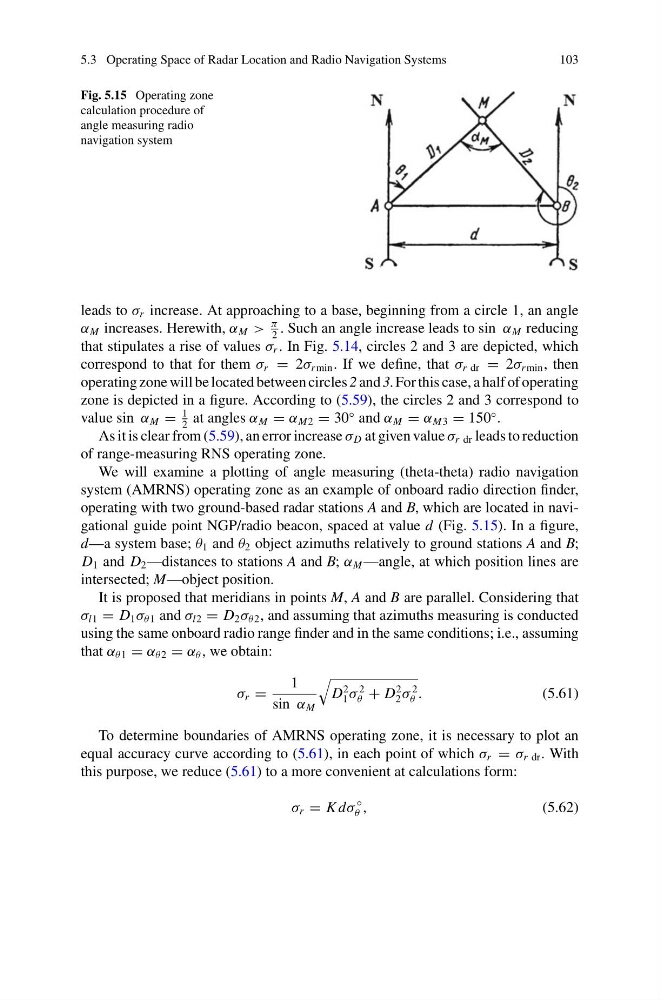
Fig. 5.15 Operating zone
calculation procedure of
angle measuring radio
navigation system
leads to σ r increase. At approaching to a base, beginning from a circle 1, an angle
α M increases. Herewith, α M >
π
2
. Such an angle increase leads to sin α M reducing
that stipulates a rise of values σ r . In Fig. 5.14, circles 2 and 3 are depicted, which
correspond to that for them σ r = 2σ r min . If we define, that σ r dr = 2σ r min , then
operating zone will be located between circles 2 and 3. For this case, a half of operating
zone is depicted in a figure. According to (5.59), the circles 2 and 3 correspond to
value sin α M =
1
2
at angles α M = α M2 = 30
◦ and α M = α M3 = 150
◦ .
As it is clear from (5.59), an error increase σ D at given value σ r dr leads to reduction
of range-measuring RNS operating zone.
We will examine a plotting of angle measuring (theta-theta) radio navigation
system (AMRNS) operating zone as an example of onboard radio direction finder,
operating with two ground-based radar stations A and B, which are located in navigational guide point NGP/radio beacon, spaced at value d (Fig. 5.15). In a figure,
d—a system base; θ 1 and θ 2 object azimuths relatively to ground stations A and B;
D 1 and D 2 —distances to stations A and B; α M —angle, at which position lines are
intersected; M—object position.
It is proposed that meridians in points M, A and B are parallel. Considering that
σ l1 = D 1 σ θ1 and σ l2 = D 2 σ θ2 , and assuming that azimuths measuring is conducted
using the same onboard radio range finder and in the same conditions; i.e., assuming
that α θ1 = α θ2 = α θ , we obtain:
σ r =
1
sin α M
D
2
1 σ
2
θ + D
2
2 σ
2
θ .
(5.61)
To determine boundaries of AMRNS operating zone, it is necessary to plot an
equal accuracy curve according to (5.61), in each point of which σ r = σ r dr . With
this purpose, we reduce (5.61) to a more convenient at calculations form:
σ r = K dσ
◦
θ ,
(5.62)
103
Fig. 5.15 Operating zone
calculation procedure of
angle measuring radio
navigation system
leads to σ r increase. At approaching to a base, beginning from a circle 1, an angle
α M increases. Herewith, α M >
π
2
. Such an angle increase leads to sin α M reducing
that stipulates a rise of values σ r . In Fig. 5.14, circles 2 and 3 are depicted, which
correspond to that for them σ r = 2σ r min . If we define, that σ r dr = 2σ r min , then
operating zone will be located between circles 2 and 3. For this case, a half of operating
zone is depicted in a figure. According to (5.59), the circles 2 and 3 correspond to
value sin α M =
1
2
at angles α M = α M2 = 30
◦ and α M = α M3 = 150
◦ .
As it is clear from (5.59), an error increase σ D at given value σ r dr leads to reduction
of range-measuring RNS operating zone.
We will examine a plotting of angle measuring (theta-theta) radio navigation
system (AMRNS) operating zone as an example of onboard radio direction finder,
operating with two ground-based radar stations A and B, which are located in navigational guide point NGP/radio beacon, spaced at value d (Fig. 5.15). In a figure,
d—a system base; θ 1 and θ 2 object azimuths relatively to ground stations A and B;
D 1 and D 2 —distances to stations A and B; α M —angle, at which position lines are
intersected; M—object position.
It is proposed that meridians in points M, A and B are parallel. Considering that
σ l1 = D 1 σ θ1 and σ l2 = D 2 σ θ2 , and assuming that azimuths measuring is conducted
using the same onboard radio range finder and in the same conditions; i.e., assuming
that α θ1 = α θ2 = α θ , we obtain:
σ r =
1
sin α M
D
2
1 σ
2
θ + D
2
2 σ
2
θ .
(5.61)
To determine boundaries of AMRNS operating zone, it is necessary to plot an
equal accuracy curve according to (5.61), in each point of which σ r = σ r dr . With
this purpose, we reduce (5.61) to a more convenient at calculations form:
σ r = K dσ
◦
θ ,
(5.62)