

86
5 Performance Characteristics of Radar Location …
F r (β) =
1 + F 2 (β t ) − 2F(β) cos
4π h
λ
sin β
.
(5.21)
Maximum and minimum (nulls) in directional pattern (5.21) will exist in those
directions β, where cosine assumes a value ±1, that gives:
• condition for maximum
sin β max =
λ
4h
(2n − 1), n = ±1, ±2, ±3, . . .
(5.22)
• condition for minimum
sin β min =
λ
4h
n, n = 0, ±1, ±2, ±3, . . .
(5.23)
The less relation λ/ h, the more frequently maximum and minimum are alternated
by resulting multi-beam directional pattern, and, consequently, the narrower lobes are
become. In other words, a multi-lobe condition is increased with wave shortening and
increasing of antenna lift above a surface (if directional pattern intersects a reflected
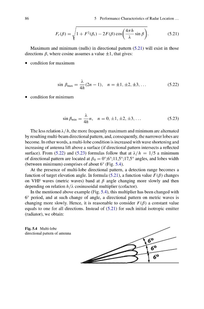
surface). From (5.22) and (5.23) formulas follow that at λ/ h = 1/5 a minimum
of directional pattern are located at β 0 = 0°;6°;11,5°;17,5° angles, and lobes width
(between minimum) comprises of about 6° (Fig. 5.4).
At the presence of multi-lobe directional pattern, a detection range becomes a
function of target elevation angle. In formula (5.21), a function value F(β) changes
on VHF waves (metric waves) band at β angle changing more slowly and then
depending on relation h/λ cosinusoidal multiplier (cofactor).
In the mentioned above example (Fig. 5.4), this multiplier has been changed with
6° period, and at such change of angle, a directional pattern on metric waves is
changing more slowly. Hence, it is reasonable to consider F(β) a constant value
equals to one for all directions. Instead of (5.21) for such initial isotropic emitter
(radiator), we obtain:
Fig. 5.4 Multi-lobe
directional pattern of antenna
5 Performance Characteristics of Radar Location …
F r (β) =
1 + F 2 (β t ) − 2F(β) cos
4π h
λ
sin β
.
(5.21)
Maximum and minimum (nulls) in directional pattern (5.21) will exist in those
directions β, where cosine assumes a value ±1, that gives:
• condition for maximum
sin β max =
λ
4h
(2n − 1), n = ±1, ±2, ±3, . . .
(5.22)
• condition for minimum
sin β min =
λ
4h
n, n = 0, ±1, ±2, ±3, . . .
(5.23)
The less relation λ/ h, the more frequently maximum and minimum are alternated
by resulting multi-beam directional pattern, and, consequently, the narrower lobes are
become. In other words, a multi-lobe condition is increased with wave shortening and
increasing of antenna lift above a surface (if directional pattern intersects a reflected
surface). From (5.22) and (5.23) formulas follow that at λ/ h = 1/5 a minimum
of directional pattern are located at β 0 = 0°;6°;11,5°;17,5° angles, and lobes width
(between minimum) comprises of about 6° (Fig. 5.4).
At the presence of multi-lobe directional pattern, a detection range becomes a
function of target elevation angle. In formula (5.21), a function value F(β) changes
on VHF waves (metric waves) band at β angle changing more slowly and then
depending on relation h/λ cosinusoidal multiplier (cofactor).
In the mentioned above example (Fig. 5.4), this multiplier has been changed with
6° period, and at such change of angle, a directional pattern on metric waves is
changing more slowly. Hence, it is reasonable to consider F(β) a constant value
equals to one for all directions. Instead of (5.21) for such initial isotropic emitter
(radiator), we obtain:
Fig. 5.4 Multi-lobe
directional pattern of antenna