

5.1 Operational Range of Radar Location and Radio Navigation Systems
85
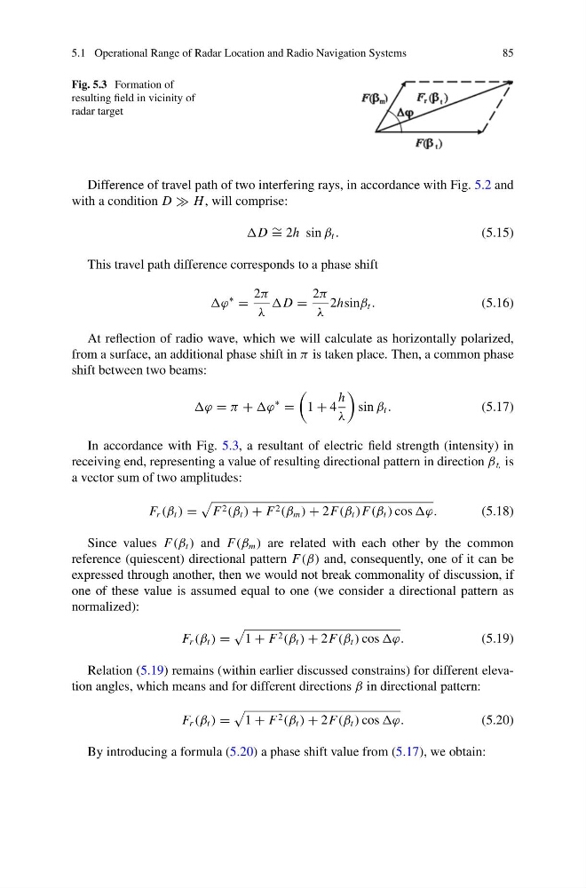
Fig. 5.3 Formation of
resulting field in vicinity of
radar target
Difference of travel path of two interfering rays, in accordance with Fig. 5.2 and
with a condition D H , will comprise:
D ∼ = 2h sin β t .
(5.15)
This travel path difference corresponds to a phase shift
ϕ
∗
=
2π
λ
D =
2π
λ
2hsinβ t .
(5.16)
At reflection of radio wave, which we will calculate as horizontally polarized,
from a surface, an additional phase shift in π is taken place. Then, a common phase
shift between two beams:
ϕ = π + ϕ
∗
=
1 + 4
h
λ
sin β t .
(5.17)
In accordance with Fig. 5.3, a resultant of electric field strength (intensity) in
receiving end, representing a value of resulting directional pattern in direction β t, is
a vector sum of two amplitudes:
F r (β t ) =
F 2 (β t ) + F 2 (β m ) + 2F(β t )F(β t ) cos ϕ.
(5.18)
Since values F(β t ) and F(β m ) are related with each other by the common
reference (quiescent) directional pattern F(β) and, consequently, one of it can be
expressed through another, then we would not break commonality of discussion, if
one of these value is assumed equal to one (we consider a directional pattern as
normalized):
F r (β t ) =
1 + F 2 (β t ) + 2F(β t ) cos ϕ.
(5.19)
Relation (5.19) remains (within earlier discussed constrains) for different elevation angles, which means and for different directions β in directional pattern:
F r (β t ) =
1 + F 2 (β t ) + 2F(β t ) cos ϕ.
(5.20)
By introducing a formula (5.20) a phase shift value from (5.17), we obtain:
85
Fig. 5.3 Formation of
resulting field in vicinity of
radar target
Difference of travel path of two interfering rays, in accordance with Fig. 5.2 and
with a condition D H , will comprise:
D ∼ = 2h sin β t .
(5.15)
This travel path difference corresponds to a phase shift
ϕ
∗
=
2π
λ
D =
2π
λ
2hsinβ t .
(5.16)
At reflection of radio wave, which we will calculate as horizontally polarized,
from a surface, an additional phase shift in π is taken place. Then, a common phase
shift between two beams:
ϕ = π + ϕ
∗
=
1 + 4
h
λ
sin β t .
(5.17)
In accordance with Fig. 5.3, a resultant of electric field strength (intensity) in
receiving end, representing a value of resulting directional pattern in direction β t, is
a vector sum of two amplitudes:
F r (β t ) =
F 2 (β t ) + F 2 (β m ) + 2F(β t )F(β t ) cos ϕ.
(5.18)
Since values F(β t ) and F(β m ) are related with each other by the common
reference (quiescent) directional pattern F(β) and, consequently, one of it can be
expressed through another, then we would not break commonality of discussion, if
one of these value is assumed equal to one (we consider a directional pattern as
normalized):
F r (β t ) =
1 + F 2 (β t ) + 2F(β t ) cos ϕ.
(5.19)
Relation (5.19) remains (within earlier discussed constrains) for different elevation angles, which means and for different directions β in directional pattern:
F r (β t ) =
1 + F 2 (β t ) + 2F(β t ) cos ϕ.
(5.20)
By introducing a formula (5.20) a phase shift value from (5.17), we obtain: