

respectively, which are Eqs. (2.83) and (2.84) of Chap. 2. At the head of the
expansion fan x ¼ c 0 t, so that p ¼ p 0 and ρ ¼ ρ 0 , and at the tail of the expansion
fan x ¼ [c 0 À ((γ + 1)/2)u 0 ]t, so that
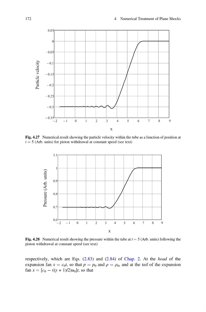
Fig. 4.27 Numerical result showing the particle velocity within the tube as a function of position at
t ¼ 5 (Arb. units) for piston withdrawal at constant speed (see text)
Fig. 4.28 Numerical result showing the pressure within the tube at t ¼ 5 (Arb. units) following the
piston withdrawal at constant speed (see text)
172
4 Numerical Treatment of Plane Shocks
expansion fan x ¼ c 0 t, so that p ¼ p 0 and ρ ¼ ρ 0 , and at the tail of the expansion
fan x ¼ [c 0 À ((γ + 1)/2)u 0 ]t, so that
Fig. 4.27 Numerical result showing the particle velocity within the tube as a function of position at
t ¼ 5 (Arb. units) for piston withdrawal at constant speed (see text)
Fig. 4.28 Numerical result showing the pressure within the tube at t ¼ 5 (Arb. units) following the
piston withdrawal at constant speed (see text)
172
4 Numerical Treatment of Plane Shocks