

p Tail
p 0
¼ 1 À
γ À 1
2
u 0
c 0
! 2γ
γÀ1
ð4:51Þ
and
ρ Tail
ρ 0
¼ 1 À
γ À 1
2
u 0
c 0
! 2
γÀ1 :
ð4:52Þ
As arbitrary values of p 0 ¼ 1 and ρ 0 ¼ 1 were used for the numerical procedure,
we find from Eqs. (4.51) and (4.52) that the pressure p and density ρ at the tail of the
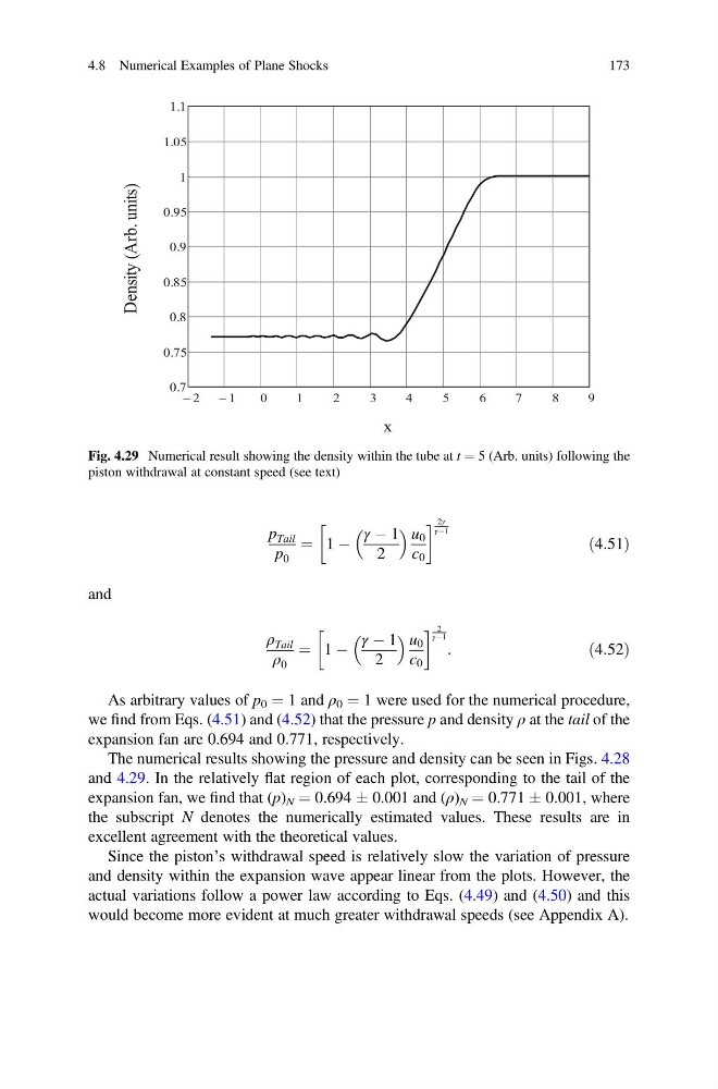
expansion fan are 0.694 and 0.771, respectively.
The numerical results showing the pressure and density can be seen in Figs. 4.28
and 4.29. In the relatively flat region of each plot, corresponding to the tail of the
expansion fan, we find that (p) N ¼ 0.694 Æ 0.001 and (ρ) N ¼ 0.771 Æ 0.001, where
the subscript N denotes the numerically estimated values. These results are in
excellent agreement with the theoretical values.
Since the piston’s withdrawal speed is relatively slow the variation of pressure
and density within the expansion wave appear linear from the plots. However, the
actual variations follow a power law according to Eqs. (4.49) and (4.50) and this
would become more evident at much greater withdrawal speeds (see Appendix A).
Fig. 4.29 Numerical result showing the density within the tube at t ¼ 5 (Arb. units) following the
piston withdrawal at constant speed (see text)
4.8 Numerical Examples of Plane Shocks
173
p 0
¼ 1 À
γ À 1
2
u 0
c 0
! 2γ
γÀ1
ð4:51Þ
and
ρ Tail
ρ 0
¼ 1 À
γ À 1
2
u 0
c 0
! 2
γÀ1 :
ð4:52Þ
As arbitrary values of p 0 ¼ 1 and ρ 0 ¼ 1 were used for the numerical procedure,
we find from Eqs. (4.51) and (4.52) that the pressure p and density ρ at the tail of the
expansion fan are 0.694 and 0.771, respectively.
The numerical results showing the pressure and density can be seen in Figs. 4.28
and 4.29. In the relatively flat region of each plot, corresponding to the tail of the
expansion fan, we find that (p) N ¼ 0.694 Æ 0.001 and (ρ) N ¼ 0.771 Æ 0.001, where
the subscript N denotes the numerically estimated values. These results are in
excellent agreement with the theoretical values.
Since the piston’s withdrawal speed is relatively slow the variation of pressure
and density within the expansion wave appear linear from the plots. However, the
actual variations follow a power law according to Eqs. (4.49) and (4.50) and this
would become more evident at much greater withdrawal speeds (see Appendix A).
Fig. 4.29 Numerical result showing the density within the tube at t ¼ 5 (Arb. units) following the
piston withdrawal at constant speed (see text)
4.8 Numerical Examples of Plane Shocks
173