

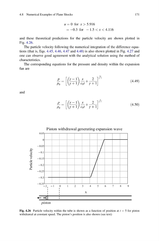
u ¼ 0 for x > 5:916
¼ À0:3 for À 1:5 < x < 4:116
and these theoretical predictions for the particle velocity are shown plotted in
Fig. 4.26.
The particle velocity following the numerical integration of the difference equations (that is, Eqs. 4.45, 4.46, 4.47 and 4.48) is also shown plotted in Fig. 4.27 and
one can observe good agreement with the analytical solution using the method of
characteristics.
The corresponding equations for the pressure and density within the expansion
fan are
p
p 0
¼
γ À 1
γ þ 1
x
c 0 t
þ
2
γ þ 1
! 2γ
γÀ1
ð4:49Þ
and
ρ
ρ 0
¼
γ À 1
γ þ 1
x
c 0 t
þ
2
γ þ 1
! 2
γÀ1
ð4:50Þ
Fig. 4.26 Particle velocity within the tube is shown as a function of position at t ¼ 5 for piston
withdrawal at constant speed. The piston’s position is also shown (see text)
4.8 Numerical Examples of Plane Shocks
171
¼ À0:3 for À 1:5 < x < 4:116
and these theoretical predictions for the particle velocity are shown plotted in
Fig. 4.26.
The particle velocity following the numerical integration of the difference equations (that is, Eqs. 4.45, 4.46, 4.47 and 4.48) is also shown plotted in Fig. 4.27 and
one can observe good agreement with the analytical solution using the method of
characteristics.
The corresponding equations for the pressure and density within the expansion
fan are
p
p 0
¼
γ À 1
γ þ 1
x
c 0 t
þ
2
γ þ 1
! 2γ
γÀ1
ð4:49Þ
and
ρ
ρ 0
¼
γ À 1
γ þ 1
x
c 0 t
þ
2
γ þ 1
! 2
γÀ1
ð4:50Þ
Fig. 4.26 Particle velocity within the tube is shown as a function of position at t ¼ 5 for piston
withdrawal at constant speed. The piston’s position is also shown (see text)
4.8 Numerical Examples of Plane Shocks
171