

Spin Transfer Torque Magnetoresistive Random Access Memory
65
coupling, can be understood as interlayer exchange coupling due to proximity effect
that could be enhanced by the roughness (or waviness) between the layers. Assuming
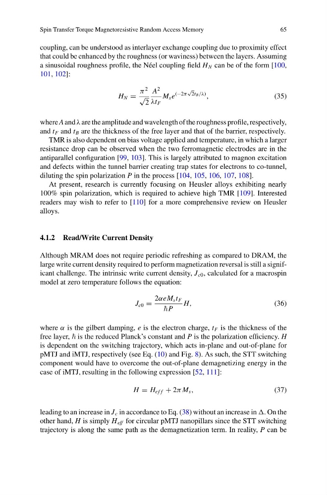
a sinusoidal roughness profile, the Néel coupling field H N can be of the form [100,
101, 102]:
H N =
π
2
√
2
A
2
λt F
M s e
(−2π
√
2t B /λ)
,
(35)
where A and λ are the amplitude and wavelength of the roughness profile, respectively,
and t F and t B are the thickness of the free layer and that of the barrier, respectively.
TMR is also dependent on bias voltage applied and temperature, in which a larger
resistance drop can be observed when the two ferromagnetic electrodes are in the
antiparallel configuration [99, 103]. This is largely attributed to magnon excitation
and defects within the tunnel barrier creating trap states for electrons to co-tunnel,
diluting the spin polarization P in the process [104, 105, 106, 107, 108].
At present, research is currently focusing on Heusler alloys exhibiting nearly
100% spin polarization, which is required to achieve high TMR [109]. Interested
readers may wish to refer to [110] for a more comprehensive review on Heusler
alloys.
4.1.2 Read/Write Current Density
Although MRAM does not require periodic refreshing as compared to DRAM, the
large write current density required to perform magnetization reversal is still a significant challenge. The intrinsic write current density, J c0 , calculated for a macrospin
model at zero temperature follows the equation:
J c0 =
2αeM s t F
P
H,
(36)
where α is the gilbert damping, e is the electron charge, t F is the thickness of the
free layer, is the reduced Planck’s constant and P is the polarization efficiency. H
is dependent on the switching trajectory, which acts in-plane and out-of-plane for
pMTJ and iMTJ, respectively (see Eq. (10) and Fig. 8). As such, the STT switching
component would have to overcome the out-of-plane demagnetizing energy in the
case of iMTJ, resulting in the following expression [52, 111]:
H = H e f f + 2π M s ,
(37)
leading to an increase in J c in accordance to Eq. (38) without an increase in . On the
other hand, H is simply H eff for circular pMTJ nanopillars since the STT switching
trajectory is along the same path as the demagnetization term. In reality, P can be
65
coupling, can be understood as interlayer exchange coupling due to proximity effect
that could be enhanced by the roughness (or waviness) between the layers. Assuming
a sinusoidal roughness profile, the Néel coupling field H N can be of the form [100,
101, 102]:
H N =
π
2
√
2
A
2
λt F
M s e
(−2π
√
2t B /λ)
,
(35)
where A and λ are the amplitude and wavelength of the roughness profile, respectively,
and t F and t B are the thickness of the free layer and that of the barrier, respectively.
TMR is also dependent on bias voltage applied and temperature, in which a larger
resistance drop can be observed when the two ferromagnetic electrodes are in the
antiparallel configuration [99, 103]. This is largely attributed to magnon excitation
and defects within the tunnel barrier creating trap states for electrons to co-tunnel,
diluting the spin polarization P in the process [104, 105, 106, 107, 108].
At present, research is currently focusing on Heusler alloys exhibiting nearly
100% spin polarization, which is required to achieve high TMR [109]. Interested
readers may wish to refer to [110] for a more comprehensive review on Heusler
alloys.
4.1.2 Read/Write Current Density
Although MRAM does not require periodic refreshing as compared to DRAM, the
large write current density required to perform magnetization reversal is still a significant challenge. The intrinsic write current density, J c0 , calculated for a macrospin
model at zero temperature follows the equation:
J c0 =
2αeM s t F
P
H,
(36)
where α is the gilbert damping, e is the electron charge, t F is the thickness of the
free layer, is the reduced Planck’s constant and P is the polarization efficiency. H
is dependent on the switching trajectory, which acts in-plane and out-of-plane for
pMTJ and iMTJ, respectively (see Eq. (10) and Fig. 8). As such, the STT switching
component would have to overcome the out-of-plane demagnetizing energy in the
case of iMTJ, resulting in the following expression [52, 111]:
H = H e f f + 2π M s ,
(37)
leading to an increase in J c in accordance to Eq. (38) without an increase in . On the
other hand, H is simply H eff for circular pMTJ nanopillars since the STT switching
trajectory is along the same path as the demagnetization term. In reality, P can be