

64
W. C. Law and S. De W. Wong
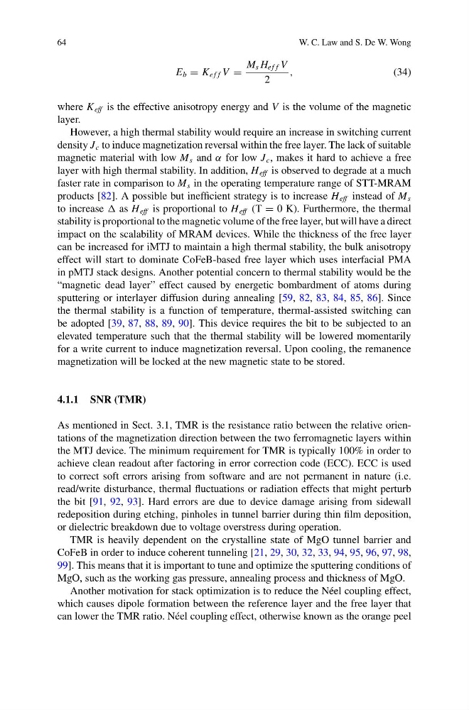
E b = K e f f V =
M s H e f f V
2
,
(34)
where K eff is the effective anisotropy energy and V is the volume of the magnetic
layer.
However, a high thermal stability would require an increase in switching current
density J c to induce magnetization reversal within the free layer. The lack of suitable
magnetic material with low M s and α for low J c , makes it hard to achieve a free
layer with high thermal stability. In addition, H eff is observed to degrade at a much
faster rate in comparison to M s in the operating temperature range of STT-MRAM
products [82]. A possible but inefficient strategy is to increase H eff instead of M s
to increase as H eff is proportional to H eff (T = 0 K). Furthermore, the thermal
stability is proportional to the magnetic volume of the free layer, but will have a direct
impact on the scalability of MRAM devices. While the thickness of the free layer
can be increased for iMTJ to maintain a high thermal stability, the bulk anisotropy
effect will start to dominate CoFeB-based free layer which uses interfacial PMA
in pMTJ stack designs. Another potential concern to thermal stability would be the
“magnetic dead layer” effect caused by energetic bombardment of atoms during
sputtering or interlayer diffusion during annealing [59, 82, 83, 84, 85, 86]. Since
the thermal stability is a function of temperature, thermal-assisted switching can
be adopted [39, 87, 88, 89, 90]. This device requires the bit to be subjected to an
elevated temperature such that the thermal stability will be lowered momentarily
for a write current to induce magnetization reversal. Upon cooling, the remanence
magnetization will be locked at the new magnetic state to be stored.
4.1.1 SNR (TMR)
As mentioned in Sect. 3.1, TMR is the resistance ratio between the relative orientations of the magnetization direction between the two ferromagnetic layers within
the MTJ device. The minimum requirement for TMR is typically 100% in order to
achieve clean readout after factoring in error correction code (ECC). ECC is used
to correct soft errors arising from software and are not permanent in nature (i.e.
read/write disturbance, thermal fluctuations or radiation effects that might perturb
the bit [91, 92, 93]. Hard errors are due to device damage arising from sidewall
redeposition during etching, pinholes in tunnel barrier during thin film deposition,
or dielectric breakdown due to voltage overstress during operation.
TMR is heavily dependent on the crystalline state of MgO tunnel barrier and
CoFeB in order to induce coherent tunneling [21, 29, 30, 32, 33, 94, 95, 96, 97, 98,
99]. This means that it is important to tune and optimize the sputtering conditions of
MgO, such as the working gas pressure, annealing process and thickness of MgO.
Another motivation for stack optimization is to reduce the Néel coupling effect,
which causes dipole formation between the reference layer and the free layer that
can lower the TMR ratio. Néel coupling effect, otherwise known as the orange peel
W. C. Law and S. De W. Wong
E b = K e f f V =
M s H e f f V
2
,
(34)
where K eff is the effective anisotropy energy and V is the volume of the magnetic
layer.
However, a high thermal stability would require an increase in switching current
density J c to induce magnetization reversal within the free layer. The lack of suitable
magnetic material with low M s and α for low J c , makes it hard to achieve a free
layer with high thermal stability. In addition, H eff is observed to degrade at a much
faster rate in comparison to M s in the operating temperature range of STT-MRAM
products [82]. A possible but inefficient strategy is to increase H eff instead of M s
to increase as H eff is proportional to H eff (T = 0 K). Furthermore, the thermal
stability is proportional to the magnetic volume of the free layer, but will have a direct
impact on the scalability of MRAM devices. While the thickness of the free layer
can be increased for iMTJ to maintain a high thermal stability, the bulk anisotropy
effect will start to dominate CoFeB-based free layer which uses interfacial PMA
in pMTJ stack designs. Another potential concern to thermal stability would be the
“magnetic dead layer” effect caused by energetic bombardment of atoms during
sputtering or interlayer diffusion during annealing [59, 82, 83, 84, 85, 86]. Since
the thermal stability is a function of temperature, thermal-assisted switching can
be adopted [39, 87, 88, 89, 90]. This device requires the bit to be subjected to an
elevated temperature such that the thermal stability will be lowered momentarily
for a write current to induce magnetization reversal. Upon cooling, the remanence
magnetization will be locked at the new magnetic state to be stored.
4.1.1 SNR (TMR)
As mentioned in Sect. 3.1, TMR is the resistance ratio between the relative orientations of the magnetization direction between the two ferromagnetic layers within
the MTJ device. The minimum requirement for TMR is typically 100% in order to
achieve clean readout after factoring in error correction code (ECC). ECC is used
to correct soft errors arising from software and are not permanent in nature (i.e.
read/write disturbance, thermal fluctuations or radiation effects that might perturb
the bit [91, 92, 93]. Hard errors are due to device damage arising from sidewall
redeposition during etching, pinholes in tunnel barrier during thin film deposition,
or dielectric breakdown due to voltage overstress during operation.
TMR is heavily dependent on the crystalline state of MgO tunnel barrier and
CoFeB in order to induce coherent tunneling [21, 29, 30, 32, 33, 94, 95, 96, 97, 98,
99]. This means that it is important to tune and optimize the sputtering conditions of
MgO, such as the working gas pressure, annealing process and thickness of MgO.
Another motivation for stack optimization is to reduce the Néel coupling effect,
which causes dipole formation between the reference layer and the free layer that
can lower the TMR ratio. Néel coupling effect, otherwise known as the orange peel