

Spin Transfer Torque Magnetoresistive Random Access Memory
53
scattering in the ferromagnetic and non-magnetic materials. On the other hand, the
resistance in CPP configuration would depend on the spin diffusion lengths in both
the ferromagnetic and non-magnetic materials.
The two current model can also be applied to the tunnel magnetoresistance
(TMR) effect, wherein the non-magnetic metal is replaced with an insulating barrier.
Therefore, the itinerant electrons will have to undergo additional tunneling effect as
opposed to instead of ohmic transport in the non-magnetic metallic spacer. Jullière’s
model was useful to describe amorphous tunnel barriers such as AlO x [23], where
the TMR can be described as:
T M R =
R AP − R P
R P
=
G P − G AP
G AP
=
2P 1 P 2
1 − P 1 P 2
.
(6)
Here, P 1 and P 2 refers to the spin polarization of the ferromagnetic electrodes,
which is further defined as:
P =
D
↑
− D
↓
D ↑ + D ↓ ,
(7)
where D
↑ and D
↓ are the DOS of the majority and minority carriers at the Fermi level.
Using the two-current model and assuming no spin-flipping occurs during tunneling,
the conductance in each channel is dependent on the Fermi’s golden rule and is
proportional to the tunneling probability. Therefore, when the two ferromagnetic
electrodes are parallel, the conductance G P has the following expression:
G P ∝ D
↑
1 D
↑
2 + D
↓
1 D
↓
2 ,
(8)
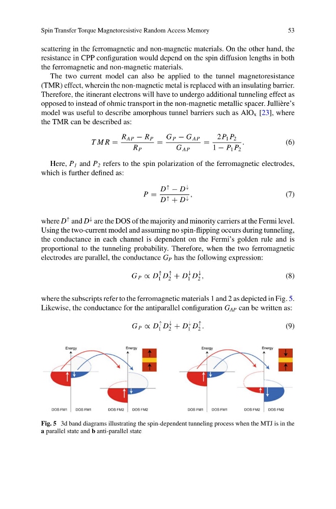
where the subscripts refer to the ferromagnetic materials 1 and 2 as depicted in Fig. 5.
Likewise, the conductance for the antiparallel configuration G AP can be written as:
G P ∝ D
↑
1 D
↓
2 + D
↓
1 D
↑
2 .
(9)
Fig. 5 3d band diagrams illustrating the spin-dependent tunneling process when the MTJ is in the
a parallel state and b anti-parallel state
53
scattering in the ferromagnetic and non-magnetic materials. On the other hand, the
resistance in CPP configuration would depend on the spin diffusion lengths in both
the ferromagnetic and non-magnetic materials.
The two current model can also be applied to the tunnel magnetoresistance
(TMR) effect, wherein the non-magnetic metal is replaced with an insulating barrier.
Therefore, the itinerant electrons will have to undergo additional tunneling effect as
opposed to instead of ohmic transport in the non-magnetic metallic spacer. Jullière’s
model was useful to describe amorphous tunnel barriers such as AlO x [23], where
the TMR can be described as:
T M R =
R AP − R P
R P
=
G P − G AP
G AP
=
2P 1 P 2
1 − P 1 P 2
.
(6)
Here, P 1 and P 2 refers to the spin polarization of the ferromagnetic electrodes,
which is further defined as:
P =
D
↑
− D
↓
D ↑ + D ↓ ,
(7)
where D
↑ and D
↓ are the DOS of the majority and minority carriers at the Fermi level.
Using the two-current model and assuming no spin-flipping occurs during tunneling,
the conductance in each channel is dependent on the Fermi’s golden rule and is
proportional to the tunneling probability. Therefore, when the two ferromagnetic
electrodes are parallel, the conductance G P has the following expression:
G P ∝ D
↑
1 D
↑
2 + D
↓
1 D
↓
2 ,
(8)
where the subscripts refer to the ferromagnetic materials 1 and 2 as depicted in Fig. 5.
Likewise, the conductance for the antiparallel configuration G AP can be written as:
G P ∝ D
↑
1 D
↓
2 + D
↓
1 D
↑
2 .
(9)
Fig. 5 3d band diagrams illustrating the spin-dependent tunneling process when the MTJ is in the
a parallel state and b anti-parallel state