

52
W. C. Law and S. De W. Wong
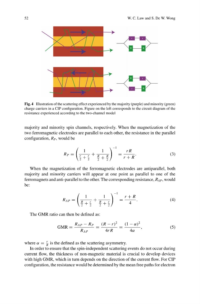
Fig. 4 Illustration of the scattering effect experienced by the majority (purple) and minority (green)
charge carriers in a CIP configuration. Figure on the left corresponds to the circuit diagram of the
resistance experienced according to the two-channel model
majority and minority spin channels, respectively. When the magnetization of the
two ferromagnetic electrodes are parallel to each other, the resistance in the parallel
configuration, R P , would be
R P =
1
r
2
+
r
2
+
1
R
2
+
R
2
−1
=
r R
r + R
.
(3)
When the magnetization of the ferromagnetic electrodes are antiparallel, both
majority and minority carriers will appear at one point as parallel to one of the
ferromagnets and anti-parallel to the other. The corresponding resistance, R AP , would
be:
R AP =
1
R
2
+
r
2
+
1
R
2
+
r
2
−1
=
r + R
4
.
(4)
The GMR ratio can then be defined as:
GMR =
R AP − R P
R AP
=
(R − r )
2
4r R
=
(1 − α)
2
4α
,
(5)
where α =
r
R
is the defined as the scattering asymmetry.
In order to ensure that the spin-independent scattering events do not occur during
current flow, the thickness of non-magnetic material is crucial to develop devices
with high GMR, which in turn depends on the direction of the current flow. For CIP
configuration, the resistance would be determined by the mean free paths for electron
W. C. Law and S. De W. Wong
Fig. 4 Illustration of the scattering effect experienced by the majority (purple) and minority (green)
charge carriers in a CIP configuration. Figure on the left corresponds to the circuit diagram of the
resistance experienced according to the two-channel model
majority and minority spin channels, respectively. When the magnetization of the
two ferromagnetic electrodes are parallel to each other, the resistance in the parallel
configuration, R P , would be
R P =
1
r
2
+
r
2
+
1
R
2
+
R
2
−1
=
r R
r + R
.
(3)
When the magnetization of the ferromagnetic electrodes are antiparallel, both
majority and minority carriers will appear at one point as parallel to one of the
ferromagnets and anti-parallel to the other. The corresponding resistance, R AP , would
be:
R AP =
1
R
2
+
r
2
+
1
R
2
+
r
2
−1
=
r + R
4
.
(4)
The GMR ratio can then be defined as:
GMR =
R AP − R P
R AP
=
(R − r )
2
4r R
=
(1 − α)
2
4α
,
(5)
where α =
r
R
is the defined as the scattering asymmetry.
In order to ensure that the spin-independent scattering events do not occur during
current flow, the thickness of non-magnetic material is crucial to develop devices
with high GMR, which in turn depends on the direction of the current flow. For CIP
configuration, the resistance would be determined by the mean free paths for electron