

364
P. Huang et al.
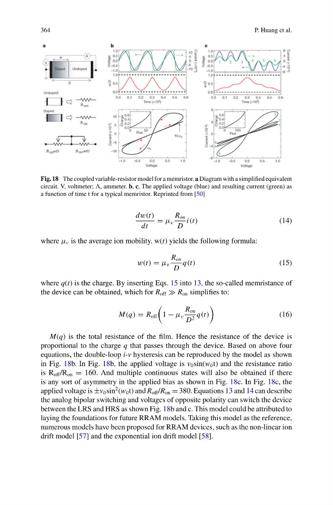
Fig. 18 The coupled variable-resistor model for a memristor. a Diagram with a simplified equivalent
circuit. V, voltmeter; A, ammeter. b, c, The applied voltage (blue) and resulting current (green) as
a function of time t for a typical memristor. Reprinted from [50]
dw(t)
dt
= μ v
R on
D
i(t)
(14)
where μ v is the average ion mobility. w(t) yields the following formula:
w(t) = μ v
R on
D
q(t)
(15)
where q(t) is the charge. By inserting Eqs. 15 into 13, the so-called memristance of
the device can be obtained, which for R off R on simplifies to:
M(q) = R off
1 − μ v
R on
D 2 q(t)
(16)
M(q) is the total resistance of the film. Hence the resistance of the device is
proportional to the charge q that passes through the device. Based on above four
equations, the double-loop i-v hysteresis can be reproduced by the model as shown
in Fig. 18b. In Fig. 18b, the applied voltage is v 0 sin(w 0 t) and the resistance ratio
is R off /R on = 160. And multiple continuous states will also be obtained if there
is any sort of asymmetry in the applied bias as shown in Fig. 18c. In Fig. 18c, the
applied voltage is ±v 0 sin
2 (w 0 t) and R off /R on = 380. Equations 13 and 14 can describe
the analog bipolar switching and voltages of opposite polarity can switch the device
between the LRS and HRS as shown Fig. 18b and c. This model could be attributed to
laying the foundations for future RRAM models. Taking this model as the reference,
numerous models have been proposed for RRAM devices, such as the non-linear ion
drift model [57] and the exponential ion drift model [58].
P. Huang et al.
Fig. 18 The coupled variable-resistor model for a memristor. a Diagram with a simplified equivalent
circuit. V, voltmeter; A, ammeter. b, c, The applied voltage (blue) and resulting current (green) as
a function of time t for a typical memristor. Reprinted from [50]
dw(t)
dt
= μ v
R on
D
i(t)
(14)
where μ v is the average ion mobility. w(t) yields the following formula:
w(t) = μ v
R on
D
q(t)
(15)
where q(t) is the charge. By inserting Eqs. 15 into 13, the so-called memristance of
the device can be obtained, which for R off R on simplifies to:
M(q) = R off
1 − μ v
R on
D 2 q(t)
(16)
M(q) is the total resistance of the film. Hence the resistance of the device is
proportional to the charge q that passes through the device. Based on above four
equations, the double-loop i-v hysteresis can be reproduced by the model as shown
in Fig. 18b. In Fig. 18b, the applied voltage is v 0 sin(w 0 t) and the resistance ratio
is R off /R on = 160. And multiple continuous states will also be obtained if there
is any sort of asymmetry in the applied bias as shown in Fig. 18c. In Fig. 18c, the
applied voltage is ±v 0 sin
2 (w 0 t) and R off /R on = 380. Equations 13 and 14 can describe
the analog bipolar switching and voltages of opposite polarity can switch the device
between the LRS and HRS as shown Fig. 18b and c. This model could be attributed to
laying the foundations for future RRAM models. Taking this model as the reference,
numerous models have been proposed for RRAM devices, such as the non-linear ion
drift model [57] and the exponential ion drift model [58].