

332
V. Y. Zhuo et al.
Instead of reducing the cell size, high density in a 3D array is achieved by increasing
the number of stacked layers.
3.1 RRAM Design Without Selector Device
The key advantages of a crosspoint array with no selector devices are the simple
fabrication process and high array density. However, it will require the RRAM device
to be self-rectifying in order to overcome the sneak path current problem.
One of the several self-rectifying concepts is the complementary resistive
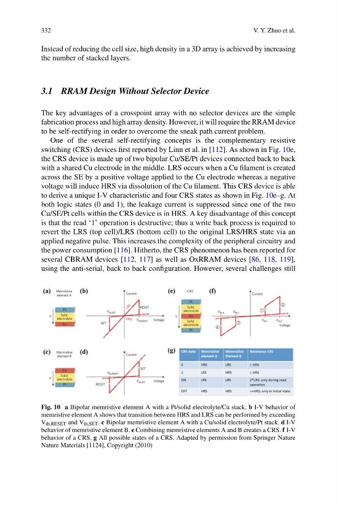
switching (CRS) devices first reported by Linn et al. in [112]. As shown in Fig. 10e,
the CRS device is made up of two bipolar Cu/SE/Pt devices connected back to back
with a shared Cu electrode in the middle. LRS occurs when a Cu filament is created
across the SE by a positive voltage applied to the Cu electrode whereas a negative
voltage will induce HRS via dissolution of the Cu filament. This CRS device is able
to derive a unique I-V characteristic and four CRS states as shown in Fig. 10e–g. At
both logic states (0 and 1), the leakage current is suppressed since one of the two
Cu/SE/Pt cells within the CRS device is in HRS. A key disadvantage of this concept
is that the read ‘1’ operation is destructive; thus a write back process is required to
revert the LRS (top cell)/LRS (bottom cell) to the original LRS/HRS state via an
applied negative pulse. This increases the complexity of the peripheral circuitry and
the power consumption [116]. Hitherto, the CRS phenomenon has been reported for
several CBRAM devices [112, 117] as well as OxRRAM devices [86, 118, 119],
using the anti-serial, back to back configuration. However, several challenges still
Fig. 10 a Bipolar memristive element A with a Pt/solid electrolyte/Cu stack. b I-V behavior of
memristive element A shows that transition between HRS and LRS can be performed by exceeding
V th,RESET and V th,SET . c Bipolar memristive element A with a Cu/solid electrolyte/Pt stack. d I-V
behavior of memristive element B. e Combining memristive elements A and B creates a CRS. f I-V
behavior of a CRS. g All possible states of a CRS. Adapted by permission from Springer Nature
Nature Materials [1124], Copyright (2010)
V. Y. Zhuo et al.
Instead of reducing the cell size, high density in a 3D array is achieved by increasing
the number of stacked layers.
3.1 RRAM Design Without Selector Device
The key advantages of a crosspoint array with no selector devices are the simple
fabrication process and high array density. However, it will require the RRAM device
to be self-rectifying in order to overcome the sneak path current problem.
One of the several self-rectifying concepts is the complementary resistive
switching (CRS) devices first reported by Linn et al. in [112]. As shown in Fig. 10e,
the CRS device is made up of two bipolar Cu/SE/Pt devices connected back to back
with a shared Cu electrode in the middle. LRS occurs when a Cu filament is created
across the SE by a positive voltage applied to the Cu electrode whereas a negative
voltage will induce HRS via dissolution of the Cu filament. This CRS device is able
to derive a unique I-V characteristic and four CRS states as shown in Fig. 10e–g. At
both logic states (0 and 1), the leakage current is suppressed since one of the two
Cu/SE/Pt cells within the CRS device is in HRS. A key disadvantage of this concept
is that the read ‘1’ operation is destructive; thus a write back process is required to
revert the LRS (top cell)/LRS (bottom cell) to the original LRS/HRS state via an
applied negative pulse. This increases the complexity of the peripheral circuitry and
the power consumption [116]. Hitherto, the CRS phenomenon has been reported for
several CBRAM devices [112, 117] as well as OxRRAM devices [86, 118, 119],
using the anti-serial, back to back configuration. However, several challenges still
Fig. 10 a Bipolar memristive element A with a Pt/solid electrolyte/Cu stack. b I-V behavior of
memristive element A shows that transition between HRS and LRS can be performed by exceeding
V th,RESET and V th,SET . c Bipolar memristive element A with a Cu/solid electrolyte/Pt stack. d I-V
behavior of memristive element B. e Combining memristive elements A and B creates a CRS. f I-V
behavior of a CRS. g All possible states of a CRS. Adapted by permission from Springer Nature
Nature Materials [1124], Copyright (2010)