

302
G. J. Lim et al.
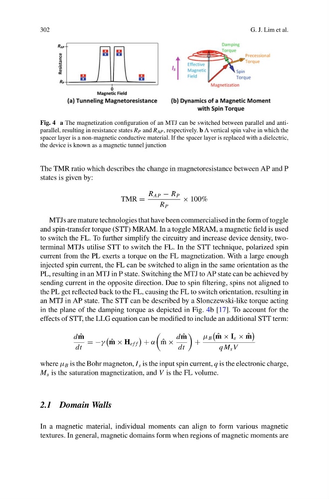
Fig. 4 a The magnetization configuration of an MTJ can be switched between parallel and antiparallel, resulting in resistance states R P and R AP , respectively. b A vertical spin valve in which the
spacer layer is a non-magnetic conductive material. If the spacer layer is replaced with a dielectric,
the device is known as a magnetic tunnel junction
The TMR ratio which describes the change in magnetoresistance between AP and P
states is given by:
TMR =
R AP − R P
R P
× 100%
MTJs are mature technologies that have been commercialised in the form of toggle
and spin-transfer torque (STT) MRAM. In a toggle MRAM, a magnetic field is used
to switch the FL. To further simplify the circuitry and increase device density, twoterminal MTJs utilise STT to switch the FL. In the STT technique, polarized spin
current from the PL exerts a torque on the FL magnetization. With a large enough
injected spin current, the FL can be switched to align in the same orientation as the
PL, resulting in an MTJ in P state. Switching the MTJ to AP state can be achieved by
sending current in the opposite direction. Due to spin filtering, spins not aligned to
the PL get reflected back to the FL, causing the FL to switch orientation, resulting in
an MTJ in AP state. The STT can be described by a Slonczewski-like torque acting
in the plane of the damping torque as depicted in Fig. 4b [17]. To account for the
effects of STT, the LLG equation can be modified to include an additional STT term:
d ˆ
m
dt
= −γ
ˆ
m × H e f f
+ α
ˆ
m ×
d ˆ
m
dt
+
μ B
ˆ
m × I s × ˆ
m
q M s V
where μ B is the Bohr magneton, I s is the input spin current, q is the electronic charge,
M s is the saturation magnetization, and V is the FL volume.
2.1 Domain Walls
In a magnetic material, individual moments can align to form various magnetic
textures. In general, magnetic domains form when regions of magnetic moments are
G. J. Lim et al.
Fig. 4 a The magnetization configuration of an MTJ can be switched between parallel and antiparallel, resulting in resistance states R P and R AP , respectively. b A vertical spin valve in which the
spacer layer is a non-magnetic conductive material. If the spacer layer is replaced with a dielectric,
the device is known as a magnetic tunnel junction
The TMR ratio which describes the change in magnetoresistance between AP and P
states is given by:
TMR =
R AP − R P
R P
× 100%
MTJs are mature technologies that have been commercialised in the form of toggle
and spin-transfer torque (STT) MRAM. In a toggle MRAM, a magnetic field is used
to switch the FL. To further simplify the circuitry and increase device density, twoterminal MTJs utilise STT to switch the FL. In the STT technique, polarized spin
current from the PL exerts a torque on the FL magnetization. With a large enough
injected spin current, the FL can be switched to align in the same orientation as the
PL, resulting in an MTJ in P state. Switching the MTJ to AP state can be achieved by
sending current in the opposite direction. Due to spin filtering, spins not aligned to
the PL get reflected back to the FL, causing the FL to switch orientation, resulting in
an MTJ in AP state. The STT can be described by a Slonczewski-like torque acting
in the plane of the damping torque as depicted in Fig. 4b [17]. To account for the
effects of STT, the LLG equation can be modified to include an additional STT term:
d ˆ
m
dt
= −γ
ˆ
m × H e f f
+ α
ˆ
m ×
d ˆ
m
dt
+
μ B
ˆ
m × I s × ˆ
m
q M s V
where μ B is the Bohr magneton, I s is the input spin current, q is the electronic charge,
M s is the saturation magnetization, and V is the FL volume.
2.1 Domain Walls
In a magnetic material, individual moments can align to form various magnetic
textures. In general, magnetic domains form when regions of magnetic moments are