

Spintronics for Neuromorphic Engineering
301
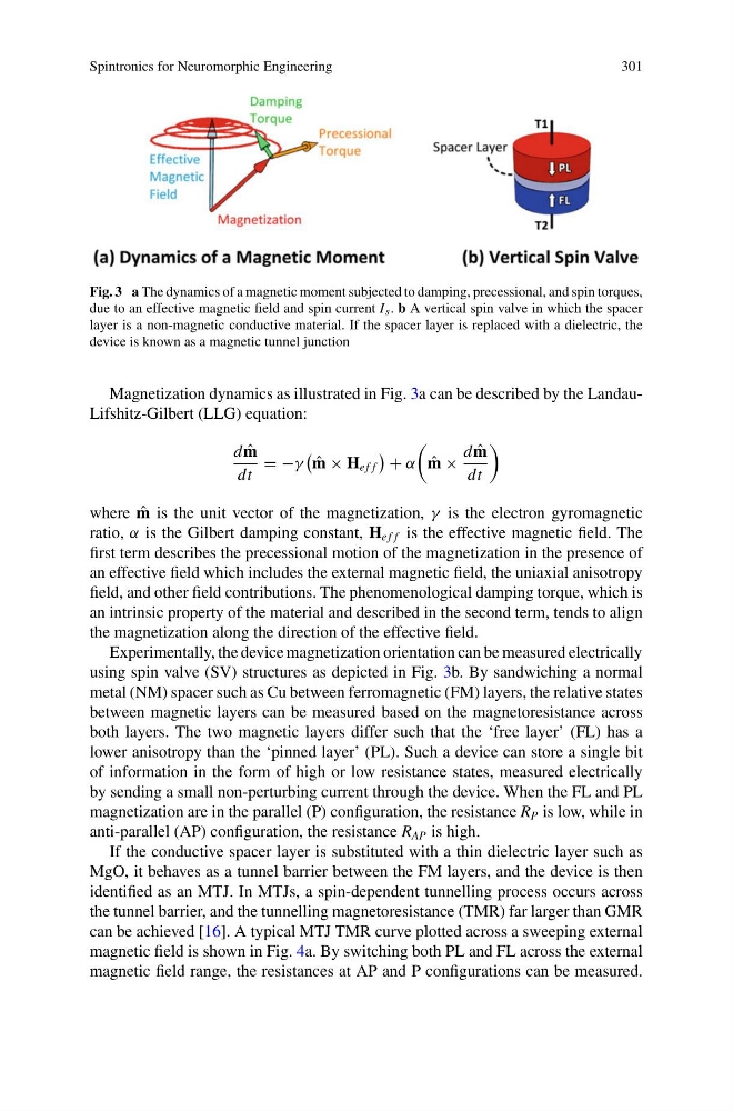
Fig. 3 a The dynamics of a magnetic moment subjected to damping, precessional, and spin torques,
due to an effective magnetic field and spin current I s . b A vertical spin valve in which the spacer
layer is a non-magnetic conductive material. If the spacer layer is replaced with a dielectric, the
device is known as a magnetic tunnel junction
Magnetization dynamics as illustrated in Fig. 3a can be described by the LandauLifshitz-Gilbert (LLG) equation:
d ˆ
m
dt
= −γ
ˆ
m × H e f f
+ α
ˆ
m ×
d ˆ
m
dt
where ˆ
m is the unit vector of the magnetization, γ is the electron gyromagnetic
ratio, α is the Gilbert damping constant, H e f f is the effective magnetic field. The
first term describes the precessional motion of the magnetization in the presence of
an effective field which includes the external magnetic field, the uniaxial anisotropy
field, and other field contributions. The phenomenological damping torque, which is
an intrinsic property of the material and described in the second term, tends to align
the magnetization along the direction of the effective field.
Experimentally, the device magnetization orientation can be measured electrically
using spin valve (SV) structures as depicted in Fig. 3b. By sandwiching a normal
metal (NM) spacer such as Cu between ferromagnetic (FM) layers, the relative states
between magnetic layers can be measured based on the magnetoresistance across
both layers. The two magnetic layers differ such that the ‘free layer’ (FL) has a
lower anisotropy than the ‘pinned layer’ (PL). Such a device can store a single bit
of information in the form of high or low resistance states, measured electrically
by sending a small non-perturbing current through the device. When the FL and PL
magnetization are in the parallel (P) configuration, the resistance R P is low, while in
anti-parallel (AP) configuration, the resistance R AP is high.
If the conductive spacer layer is substituted with a thin dielectric layer such as
MgO, it behaves as a tunnel barrier between the FM layers, and the device is then
identified as an MTJ. In MTJs, a spin-dependent tunnelling process occurs across
the tunnel barrier, and the tunnelling magnetoresistance (TMR) far larger than GMR
can be achieved [16]. A typical MTJ TMR curve plotted across a sweeping external
magnetic field is shown in Fig. 4a. By switching both PL and FL across the external
magnetic field range, the resistances at AP and P configurations can be measured.
301
Fig. 3 a The dynamics of a magnetic moment subjected to damping, precessional, and spin torques,
due to an effective magnetic field and spin current I s . b A vertical spin valve in which the spacer
layer is a non-magnetic conductive material. If the spacer layer is replaced with a dielectric, the
device is known as a magnetic tunnel junction
Magnetization dynamics as illustrated in Fig. 3a can be described by the LandauLifshitz-Gilbert (LLG) equation:
d ˆ
m
dt
= −γ
ˆ
m × H e f f
+ α
ˆ
m ×
d ˆ
m
dt
where ˆ
m is the unit vector of the magnetization, γ is the electron gyromagnetic
ratio, α is the Gilbert damping constant, H e f f is the effective magnetic field. The
first term describes the precessional motion of the magnetization in the presence of
an effective field which includes the external magnetic field, the uniaxial anisotropy
field, and other field contributions. The phenomenological damping torque, which is
an intrinsic property of the material and described in the second term, tends to align
the magnetization along the direction of the effective field.
Experimentally, the device magnetization orientation can be measured electrically
using spin valve (SV) structures as depicted in Fig. 3b. By sandwiching a normal
metal (NM) spacer such as Cu between ferromagnetic (FM) layers, the relative states
between magnetic layers can be measured based on the magnetoresistance across
both layers. The two magnetic layers differ such that the ‘free layer’ (FL) has a
lower anisotropy than the ‘pinned layer’ (PL). Such a device can store a single bit
of information in the form of high or low resistance states, measured electrically
by sending a small non-perturbing current through the device. When the FL and PL
magnetization are in the parallel (P) configuration, the resistance R P is low, while in
anti-parallel (AP) configuration, the resistance R AP is high.
If the conductive spacer layer is substituted with a thin dielectric layer such as
MgO, it behaves as a tunnel barrier between the FM layers, and the device is then
identified as an MTJ. In MTJs, a spin-dependent tunnelling process occurs across
the tunnel barrier, and the tunnelling magnetoresistance (TMR) far larger than GMR
can be achieved [16]. A typical MTJ TMR curve plotted across a sweeping external
magnetic field is shown in Fig. 4a. By switching both PL and FL across the external
magnetic field range, the resistances at AP and P configurations can be measured.