

3D Nanomagnetic Logic
279
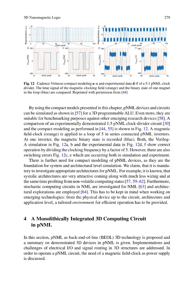
Fig. 12 Cadence Virtuose compact modeling a–c and experimental data d–f of a 5:1 pNML clock
divider. The time signal of the magnetic clocking field (orange) and the binary state of one magnet
in the loop (blue) are compared. Reprinted with permission from [44]
By using the compact models presented in this chapter, pNML devices and circuits
can be simulated as shown in [57] for a 3D programmable ALU. Even more, they are
suitable for benchmarking purposes against other emerging research devices [58]. A
comparison of an experimentally demonstrated 1:5 pNML clock-divider circuit [30]
and the compact modeling as performed in [44, 55] is shown in Fig. 12. A magnetic
field-clock (orange) is applied to a loop of 5 in series connected pNML inverters.
At one inverter, the magnetic binary state is recorded (blue). Both, the VerilogA simulation in Fig. 12a, b and the experimental data in Fig. 12d, f show correct
operation by dividing the clocking frequency by a factor of 5. However, there are also
switching errors Fig. 12c, e which are occurring both in simulation and experiment.
There is further need for compact modeling of pNML devices, as they are the
foundation for system and architectural level simulation. We claim, that it is mandatory to investigate appropriate architectures for pNML. For example, it is known, that
systolic architectures are very attractive coming along with much less wiring and at
the same time profiting from non-volatile computing states [57, 59–62]. Furthermore,
stochastic computing circuits in NML are investigated for NML [63] and architectural explorations are employed [64]. This has to be kept in mind when working on
emerging technologies: from the physical device up to the circuit, architecture and
application level, a tailored environment for efficient operation has to be provided.
4 A Monolithically Integrated 3D Computing Circuit
in pNML
In this section, pNML as back-end-of-line (BEOL) 3D technology is proposed and
a summary on demonstrated 3D devices in pNML is given. Implementations and
challenges of electrical I/O and signal routing in 3D structures are addressed. In
order to operate a pNML circuit, the need of a magnetic field-clock as power supply
is discussed.
279
Fig. 12 Cadence Virtuose compact modeling a–c and experimental data d–f of a 5:1 pNML clock
divider. The time signal of the magnetic clocking field (orange) and the binary state of one magnet
in the loop (blue) are compared. Reprinted with permission from [44]
By using the compact models presented in this chapter, pNML devices and circuits
can be simulated as shown in [57] for a 3D programmable ALU. Even more, they are
suitable for benchmarking purposes against other emerging research devices [58]. A
comparison of an experimentally demonstrated 1:5 pNML clock-divider circuit [30]
and the compact modeling as performed in [44, 55] is shown in Fig. 12. A magnetic
field-clock (orange) is applied to a loop of 5 in series connected pNML inverters.
At one inverter, the magnetic binary state is recorded (blue). Both, the VerilogA simulation in Fig. 12a, b and the experimental data in Fig. 12d, f show correct
operation by dividing the clocking frequency by a factor of 5. However, there are also
switching errors Fig. 12c, e which are occurring both in simulation and experiment.
There is further need for compact modeling of pNML devices, as they are the
foundation for system and architectural level simulation. We claim, that it is mandatory to investigate appropriate architectures for pNML. For example, it is known, that
systolic architectures are very attractive coming along with much less wiring and at
the same time profiting from non-volatile computing states [57, 59–62]. Furthermore,
stochastic computing circuits in NML are investigated for NML [63] and architectural explorations are employed [64]. This has to be kept in mind when working on
emerging technologies: from the physical device up to the circuit, architecture and
application level, a tailored environment for efficient operation has to be provided.
4 A Monolithically Integrated 3D Computing Circuit
in pNML
In this section, pNML as back-end-of-line (BEOL) 3D technology is proposed and
a summary on demonstrated 3D devices in pNML is given. Implementations and
challenges of electrical I/O and signal routing in 3D structures are addressed. In
order to operate a pNML circuit, the need of a magnetic field-clock as power supply
is discussed.