

254
S. Goolaup et al.
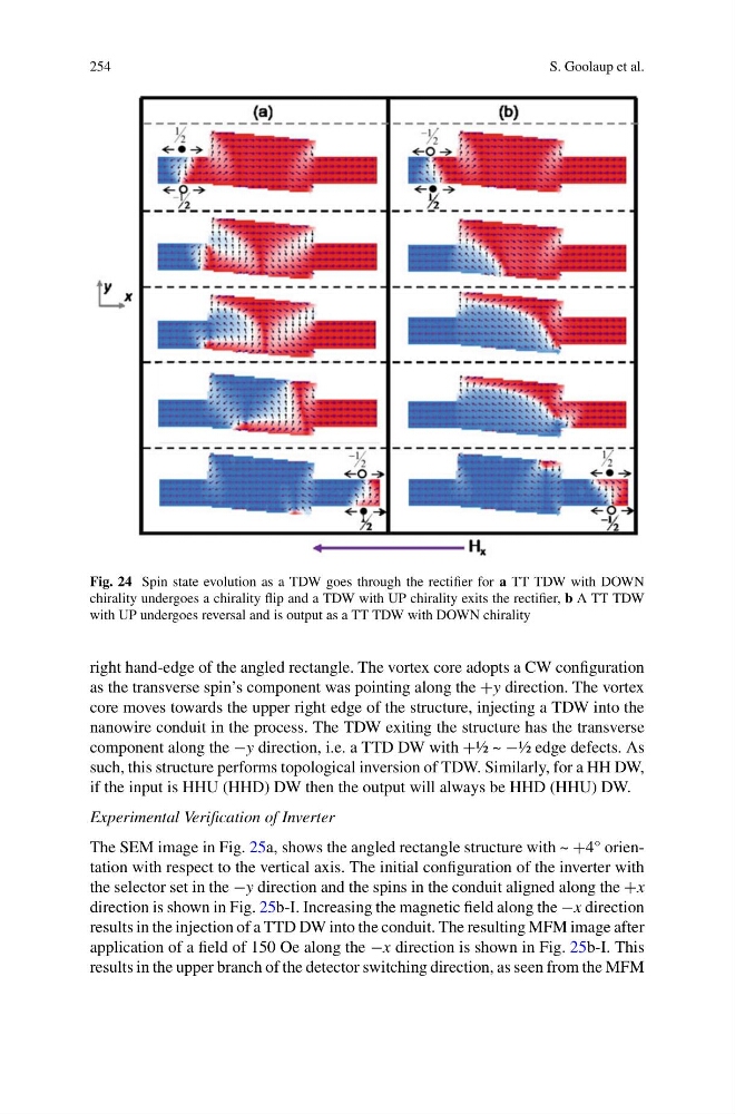
Fig. 24 Spin state evolution as a TDW goes through the rectifier for a TT TDW with DOWN
chirality undergoes a chirality flip and a TDW with UP chirality exits the rectifier, b A TT TDW
with UP undergoes reversal and is output as a TT TDW with DOWN chirality
right hand-edge of the angled rectangle. The vortex core adopts a CW configuration
as the transverse spin’s component was pointing along the +y direction. The vortex
core moves towards the upper right edge of the structure, injecting a TDW into the
nanowire conduit in the process. The TDW exiting the structure has the transverse
component along the −y direction, i.e. a TTD DW with +½ ~ −½ edge defects. As
such, this structure performs topological inversion of TDW. Similarly, for a HH DW,
if the input is HHU (HHD) DW then the output will always be HHD (HHU) DW.
Experimental Verification of Inverter
The SEM image in Fig. 25a, shows the angled rectangle structure with ~ +4° orientation with respect to the vertical axis. The initial configuration of the inverter with
the selector set in the −y direction and the spins in the conduit aligned along the +x
direction is shown in Fig. 25b-I. Increasing the magnetic field along the −x direction
results in the injection of a TTD DW into the conduit. The resulting MFM image after
application of a field of 150 Oe along the −x direction is shown in Fig. 25b-I. This
results in the upper branch of the detector switching direction, as seen from the MFM
S. Goolaup et al.
Fig. 24 Spin state evolution as a TDW goes through the rectifier for a TT TDW with DOWN
chirality undergoes a chirality flip and a TDW with UP chirality exits the rectifier, b A TT TDW
with UP undergoes reversal and is output as a TT TDW with DOWN chirality
right hand-edge of the angled rectangle. The vortex core adopts a CW configuration
as the transverse spin’s component was pointing along the +y direction. The vortex
core moves towards the upper right edge of the structure, injecting a TDW into the
nanowire conduit in the process. The TDW exiting the structure has the transverse
component along the −y direction, i.e. a TTD DW with +½ ~ −½ edge defects. As
such, this structure performs topological inversion of TDW. Similarly, for a HH DW,
if the input is HHU (HHD) DW then the output will always be HHD (HHU) DW.
Experimental Verification of Inverter
The SEM image in Fig. 25a, shows the angled rectangle structure with ~ +4° orientation with respect to the vertical axis. The initial configuration of the inverter with
the selector set in the −y direction and the spins in the conduit aligned along the +x
direction is shown in Fig. 25b-I. Increasing the magnetic field along the −x direction
results in the injection of a TTD DW into the conduit. The resulting MFM image after
application of a field of 150 Oe along the −x direction is shown in Fig. 25b-I. This
results in the upper branch of the detector switching direction, as seen from the MFM