

Domain Wall Programmable Magnetic Logic
255
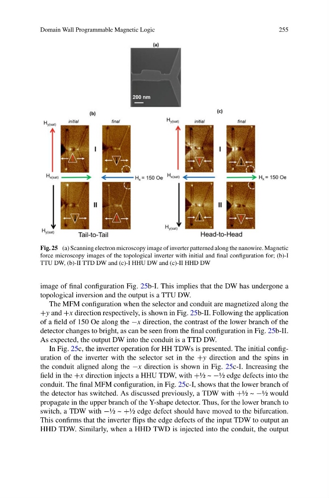
Fig. 25 (a) Scanning electron microscopy image of inverter patterned along the nanowire. Magnetic
force microscopy images of the topological inverter with initial and final configuration for; (b)-I
TTU DW, (b)-II TTD DW and (c)-I HHU DW and (c)-II HHD DW
image of final configuration Fig. 25b-I. This implies that the DW has undergone a
topological inversion and the output is a TTU DW.
The MFM configuration when the selector and conduit are magnetized along the
+y and +x direction respectively, is shown in Fig. 25b-II. Following the application
of a field of 150 Oe along the −x direction, the contrast of the lower branch of the
detector changes to bright, as can be seen from the final configuration in Fig. 25b-II.
As expected, the output DW into the conduit is a TTD DW.
In Fig. 25c, the inverter operation for HH TDWs is presented. The initial configuration of the inverter with the selector set in the +y direction and the spins in
the conduit aligned along the −x direction is shown in Fig. 25c-I. Increasing the
field in the +x direction injects a HHU TDW, with +½ ~ −½ edge defects into the
conduit. The final MFM configuration, in Fig. 25c-I, shows that the lower branch of
the detector has switched. As discussed previously, a TDW with +½ ~ −½ would
propagate in the upper branch of the Y-shape detector. Thus, for the lower branch to
switch, a TDW with −½ ~ +½ edge defect should have moved to the bifurcation.
This confirms that the inverter flips the edge defects of the input TDW to output an
HHD TDW. Similarly, when a HHD TWD is injected into the conduit, the output
255
Fig. 25 (a) Scanning electron microscopy image of inverter patterned along the nanowire. Magnetic
force microscopy images of the topological inverter with initial and final configuration for; (b)-I
TTU DW, (b)-II TTD DW and (c)-I HHU DW and (c)-II HHD DW
image of final configuration Fig. 25b-I. This implies that the DW has undergone a
topological inversion and the output is a TTU DW.
The MFM configuration when the selector and conduit are magnetized along the
+y and +x direction respectively, is shown in Fig. 25b-II. Following the application
of a field of 150 Oe along the −x direction, the contrast of the lower branch of the
detector changes to bright, as can be seen from the final configuration in Fig. 25b-II.
As expected, the output DW into the conduit is a TTD DW.
In Fig. 25c, the inverter operation for HH TDWs is presented. The initial configuration of the inverter with the selector set in the +y direction and the spins in
the conduit aligned along the −x direction is shown in Fig. 25c-I. Increasing the
field in the +x direction injects a HHU TDW, with +½ ~ −½ edge defects into the
conduit. The final MFM configuration, in Fig. 25c-I, shows that the lower branch of
the detector has switched. As discussed previously, a TDW with +½ ~ −½ would
propagate in the upper branch of the Y-shape detector. Thus, for the lower branch to
switch, a TDW with −½ ~ +½ edge defect should have moved to the bifurcation.
This confirms that the inverter flips the edge defects of the input TDW to output an
HHD TDW. Similarly, when a HHD TWD is injected into the conduit, the output