

Domain Wall Programmable Magnetic Logic
253
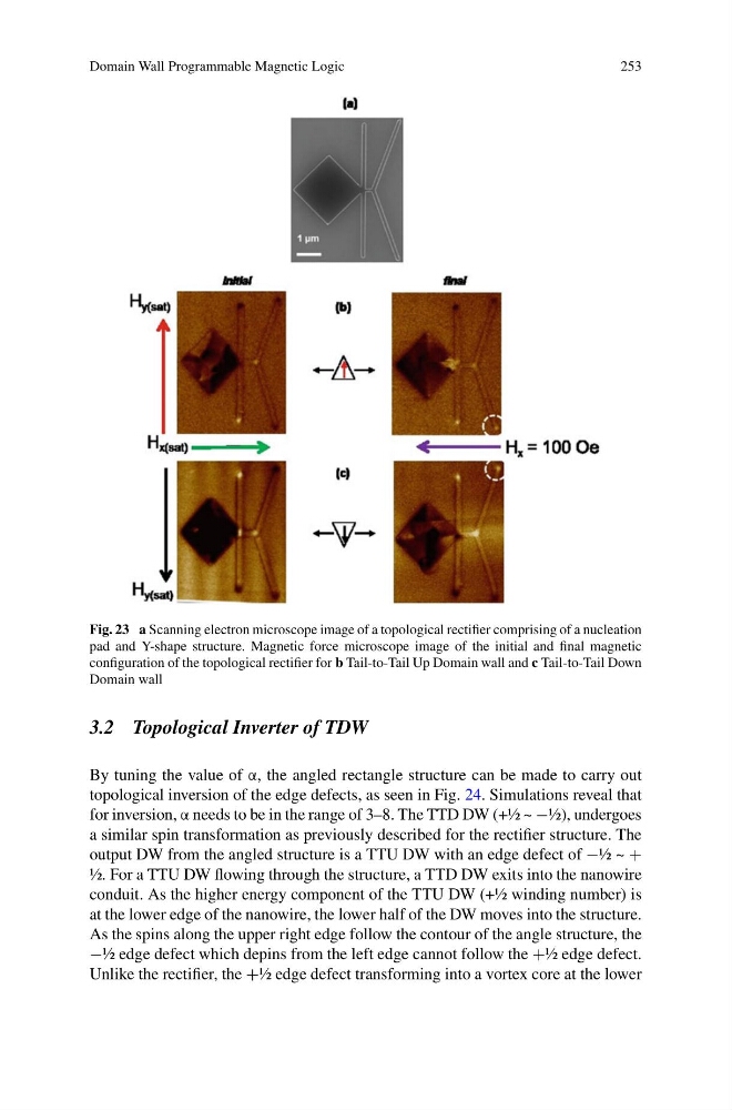
Fig. 23 a Scanning electron microscope image of a topological rectifier comprising of a nucleation
pad and Y-shape structure. Magnetic force microscope image of the initial and final magnetic
configuration of the topological rectifier for b Tail-to-Tail Up Domain wall and c Tail-to-Tail Down
Domain wall
3.2 Topological Inverter of TDW
By tuning the value of α, the angled rectangle structure can be made to carry out
topological inversion of the edge defects, as seen in Fig. 24. Simulations reveal that
for inversion, α needs to be in the range of 3–8. The TTD DW (+½ ~ −½), undergoes
a similar spin transformation as previously described for the rectifier structure. The
output DW from the angled structure is a TTU DW with an edge defect of −½ ~ +
½. For a TTU DW flowing through the structure, a TTD DW exits into the nanowire
conduit. As the higher energy component of the TTU DW (+½ winding number) is
at the lower edge of the nanowire, the lower half of the DW moves into the structure.
As the spins along the upper right edge follow the contour of the angle structure, the
−½ edge defect which depins from the left edge cannot follow the +½ edge defect.
Unlike the rectifier, the +½ edge defect transforming into a vortex core at the lower
253
Fig. 23 a Scanning electron microscope image of a topological rectifier comprising of a nucleation
pad and Y-shape structure. Magnetic force microscope image of the initial and final magnetic
configuration of the topological rectifier for b Tail-to-Tail Up Domain wall and c Tail-to-Tail Down
Domain wall
3.2 Topological Inverter of TDW
By tuning the value of α, the angled rectangle structure can be made to carry out
topological inversion of the edge defects, as seen in Fig. 24. Simulations reveal that
for inversion, α needs to be in the range of 3–8. The TTD DW (+½ ~ −½), undergoes
a similar spin transformation as previously described for the rectifier structure. The
output DW from the angled structure is a TTU DW with an edge defect of −½ ~ +
½. For a TTU DW flowing through the structure, a TTD DW exits into the nanowire
conduit. As the higher energy component of the TTU DW (+½ winding number) is
at the lower edge of the nanowire, the lower half of the DW moves into the structure.
As the spins along the upper right edge follow the contour of the angle structure, the
−½ edge defect which depins from the left edge cannot follow the +½ edge defect.
Unlike the rectifier, the +½ edge defect transforming into a vortex core at the lower