

250
S. Goolaup et al.
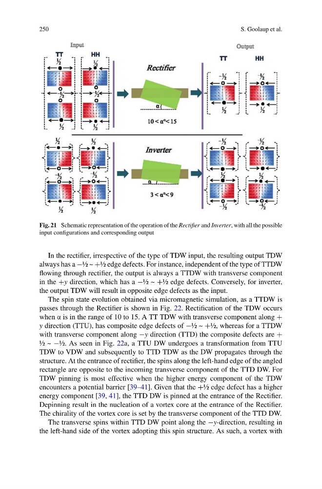
Fig. 21 Schematic representation of the operation of the Rectifier and Inverter, with all the possible
input configurations and corresponding output
In the rectifier, irrespective of the type of TDW input, the resulting output TDW
always has a −½ ~ +½ edge defects. For instance, independent of the type of TTDW
flowing through rectifier, the output is always a TTDW with transverse component
in the +y direction, which has a −½ ~ +½ edge defects. Conversely, for inverter,
the output TDW will result in opposite edge defects as the input.
The spin state evolution obtained via micromagnetic simulation, as a TTDW is
passes through the Rectifier is shown in Fig. 22. Rectification of the TDW occurs
when α is in the range of 10 to 15. A TT TDW with transverse component along +
y direction (TTU), has composite edge defects of −½ ~ +½, whereas for a TTDW
with transverse component along −y direction (TTD) the composite defects are +
½ ~ −½. As seen in Fig. 22a, a TTU DW undergoes a transformation from TTU
TDW to VDW and subsequently to TTD TDW as the DW propagates through the
structure. At the entrance of rectifier, the spins along the left-hand edge of the angled
rectangle are opposite to the incoming transverse component of the TTD DW. For
TDW pinning is most effective when the higher energy component of the TDW
encounters a potential barrier [39–41]. Given that the +½ edge defect has a higher
energy component [39, 41], the TTD DW is pinned at the entrance of the Rectifier.
Depinning result in the nucleation of a vortex core at the entrance of the Rectifier.
The chirality of the vortex core is set by the transverse component of the TTD DW.
The transverse spins within TTD DW point along the −y-direction, resulting in
the left-hand side of the vortex adopting this spin structure. As such, a vortex with
S. Goolaup et al.
Fig. 21 Schematic representation of the operation of the Rectifier and Inverter, with all the possible
input configurations and corresponding output
In the rectifier, irrespective of the type of TDW input, the resulting output TDW
always has a −½ ~ +½ edge defects. For instance, independent of the type of TTDW
flowing through rectifier, the output is always a TTDW with transverse component
in the +y direction, which has a −½ ~ +½ edge defects. Conversely, for inverter,
the output TDW will result in opposite edge defects as the input.
The spin state evolution obtained via micromagnetic simulation, as a TTDW is
passes through the Rectifier is shown in Fig. 22. Rectification of the TDW occurs
when α is in the range of 10 to 15. A TT TDW with transverse component along +
y direction (TTU), has composite edge defects of −½ ~ +½, whereas for a TTDW
with transverse component along −y direction (TTD) the composite defects are +
½ ~ −½. As seen in Fig. 22a, a TTU DW undergoes a transformation from TTU
TDW to VDW and subsequently to TTD TDW as the DW propagates through the
structure. At the entrance of rectifier, the spins along the left-hand edge of the angled
rectangle are opposite to the incoming transverse component of the TTD DW. For
TDW pinning is most effective when the higher energy component of the TDW
encounters a potential barrier [39–41]. Given that the +½ edge defect has a higher
energy component [39, 41], the TTD DW is pinned at the entrance of the Rectifier.
Depinning result in the nucleation of a vortex core at the entrance of the Rectifier.
The chirality of the vortex core is set by the transverse component of the TTD DW.
The transverse spins within TTD DW point along the −y-direction, resulting in
the left-hand side of the vortex adopting this spin structure. As such, a vortex with