

Domain Wall Programmable Magnetic Logic
251
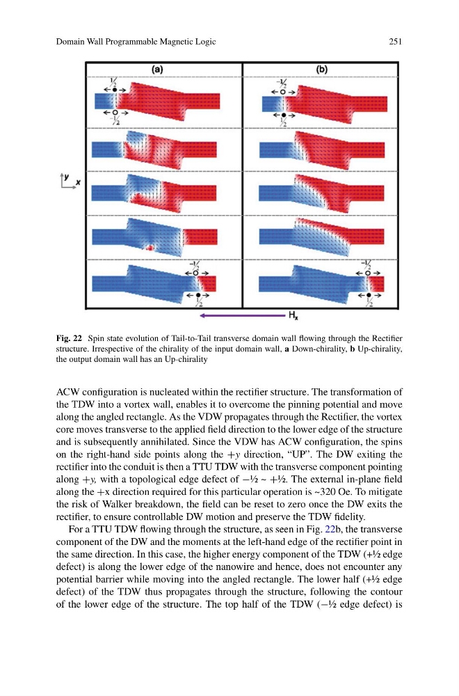
Fig. 22 Spin state evolution of Tail-to-Tail transverse domain wall flowing through the Rectifier
structure. Irrespective of the chirality of the input domain wall, a Down-chirality, b Up-chirality,
the output domain wall has an Up-chirality
ACW configuration is nucleated within the rectifier structure. The transformation of
the TDW into a vortex wall, enables it to overcome the pinning potential and move
along the angled rectangle. As the VDW propagates through the Rectifier, the vortex
core moves transverse to the applied field direction to the lower edge of the structure
and is subsequently annihilated. Since the VDW has ACW configuration, the spins
on the right-hand side points along the +y direction, “UP”. The DW exiting the
rectifier into the conduit is then a TTU TDW with the transverse component pointing
along +y, with a topological edge defect of −½ ~ +½. The external in-plane field
along the +x direction required for this particular operation is ~320 Oe. To mitigate
the risk of Walker breakdown, the field can be reset to zero once the DW exits the
rectifier, to ensure controllable DW motion and preserve the TDW fidelity.
For a TTU TDW flowing through the structure, as seen in Fig. 22b, the transverse
component of the DW and the moments at the left-hand edge of the rectifier point in
the same direction. In this case, the higher energy component of the TDW (+½ edge
defect) is along the lower edge of the nanowire and hence, does not encounter any
potential barrier while moving into the angled rectangle. The lower half (+½ edge
defect) of the TDW thus propagates through the structure, following the contour
of the lower edge of the structure. The top half of the TDW (−½ edge defect) is
251
Fig. 22 Spin state evolution of Tail-to-Tail transverse domain wall flowing through the Rectifier
structure. Irrespective of the chirality of the input domain wall, a Down-chirality, b Up-chirality,
the output domain wall has an Up-chirality
ACW configuration is nucleated within the rectifier structure. The transformation of
the TDW into a vortex wall, enables it to overcome the pinning potential and move
along the angled rectangle. As the VDW propagates through the Rectifier, the vortex
core moves transverse to the applied field direction to the lower edge of the structure
and is subsequently annihilated. Since the VDW has ACW configuration, the spins
on the right-hand side points along the +y direction, “UP”. The DW exiting the
rectifier into the conduit is then a TTU TDW with the transverse component pointing
along +y, with a topological edge defect of −½ ~ +½. The external in-plane field
along the +x direction required for this particular operation is ~320 Oe. To mitigate
the risk of Walker breakdown, the field can be reset to zero once the DW exits the
rectifier, to ensure controllable DW motion and preserve the TDW fidelity.
For a TTU TDW flowing through the structure, as seen in Fig. 22b, the transverse
component of the DW and the moments at the left-hand edge of the rectifier point in
the same direction. In this case, the higher energy component of the TDW (+½ edge
defect) is along the lower edge of the nanowire and hence, does not encounter any
potential barrier while moving into the angled rectangle. The lower half (+½ edge
defect) of the TDW thus propagates through the structure, following the contour
of the lower edge of the structure. The top half of the TDW (−½ edge defect) is