

Domain Wall Programmable Magnetic Logic
249
Table 3 NOR and OR Truth table formed based on the logic operations of the device showing
NOR and OR functionalities
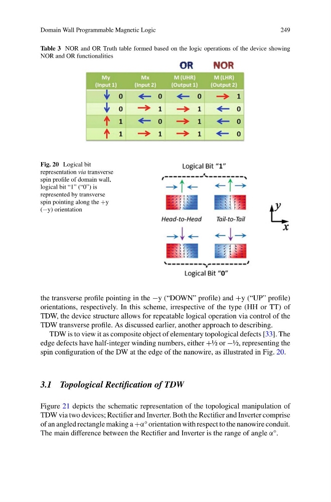
Fig. 20 Logical bit
representation via transverse
spin profile of domain wall,
logical bit “1” (“0”) is
represented by transverse
spin pointing along the +y
(−y) orientation
the transverse profile pointing in the −y (“DOWN” profile) and +y (“UP” profile)
orientations, respectively. In this scheme, irrespective of the type (HH or TT) of
TDW, the device structure allows for repeatable logical operation via control of the
TDW transverse profile. As discussed earlier, another approach to describing.
TDW is to view it as composite object of elementary topological defects [33]. The
edge defects have half-integer winding numbers, either +½ or −½, representing the
spin configuration of the DW at the edge of the nanowire, as illustrated in Fig. 20.
3.1 Topological Rectification of TDW
Figure 21 depicts the schematic representation of the topological manipulation of
TDW via two devices; Rectifier and Inverter. Both the Rectifier and Inverter comprise
of an angled rectangle making a +α° orientation with respect to the nanowire conduit.
The main difference between the Rectifier and Inverter is the range of angle α°.
249
Table 3 NOR and OR Truth table formed based on the logic operations of the device showing
NOR and OR functionalities
Fig. 20 Logical bit
representation via transverse
spin profile of domain wall,
logical bit “1” (“0”) is
represented by transverse
spin pointing along the +y
(−y) orientation
the transverse profile pointing in the −y (“DOWN” profile) and +y (“UP” profile)
orientations, respectively. In this scheme, irrespective of the type (HH or TT) of
TDW, the device structure allows for repeatable logical operation via control of the
TDW transverse profile. As discussed earlier, another approach to describing.
TDW is to view it as composite object of elementary topological defects [33]. The
edge defects have half-integer winding numbers, either +½ or −½, representing the
spin configuration of the DW at the edge of the nanowire, as illustrated in Fig. 20.
3.1 Topological Rectification of TDW
Figure 21 depicts the schematic representation of the topological manipulation of
TDW via two devices; Rectifier and Inverter. Both the Rectifier and Inverter comprise
of an angled rectangle making a +α° orientation with respect to the nanowire conduit.
The main difference between the Rectifier and Inverter is the range of angle α°.