

248
S. Goolaup et al.
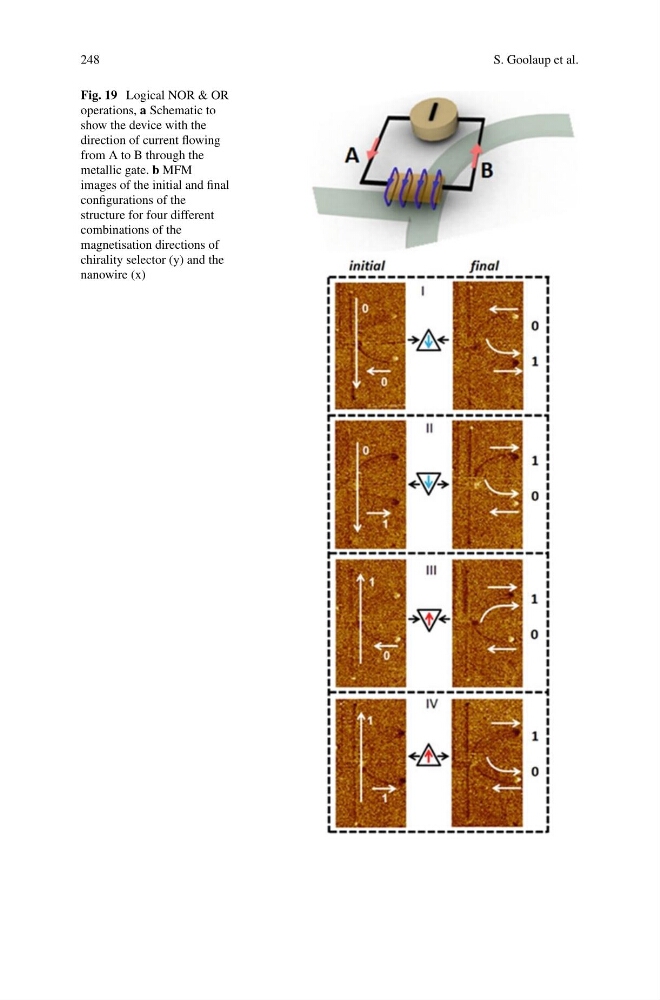
Fig. 19 Logical NOR & OR
operations, a Schematic to
show the device with the
direction of current flowing
from A to B through the
metallic gate. b MFM
images of the initial and final
configurations of the
structure for four different
combinations of the
magnetisation directions of
chirality selector (y) and the
nanowire (x)
S. Goolaup et al.
Fig. 19 Logical NOR & OR
operations, a Schematic to
show the device with the
direction of current flowing
from A to B through the
metallic gate. b MFM
images of the initial and final
configurations of the
structure for four different
combinations of the
magnetisation directions of
chirality selector (y) and the
nanowire (x)