

Domain Wall Programmable Magnetic Logic
239
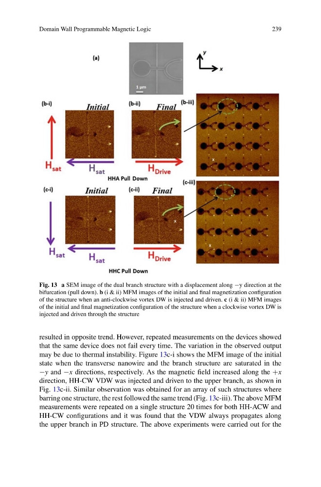
Fig. 13 a SEM image of the dual branch structure with a displacement along −y direction at the
bifurcation (pull down). b (i & ii) MFM images of the initial and final magnetization configuration
of the structure when an anti-clockwise vortex DW is injected and driven. c (i & ii) MFM images
of the initial and final magnetization configuration of the structure when a clockwise vortex DW is
injected and driven through the structure
resulted in opposite trend. However, repeated measurements on the devices showed
that the same device does not fail every time. The variation in the observed output
may be due to thermal instability. Figure 13c-i shows the MFM image of the initial
state when the transverse nanowire and the branch structure are saturated in the
−y and −x directions, respectively. As the magnetic field increased along the +x
direction, HH-CW VDW was injected and driven to the upper branch, as shown in
Fig. 13c-ii. Similar observation was obtained for an array of such structures where
barring one structure, the rest followed the same trend (Fig. 13c-iii). The above MFM
measurements were repeated on a single structure 20 times for both HH-ACW and
HH-CW configurations and it was found that the VDW always propagates along
the upper branch in PD structure. The above experiments were carried out for the
239
Fig. 13 a SEM image of the dual branch structure with a displacement along −y direction at the
bifurcation (pull down). b (i & ii) MFM images of the initial and final magnetization configuration
of the structure when an anti-clockwise vortex DW is injected and driven. c (i & ii) MFM images
of the initial and final magnetization configuration of the structure when a clockwise vortex DW is
injected and driven through the structure
resulted in opposite trend. However, repeated measurements on the devices showed
that the same device does not fail every time. The variation in the observed output
may be due to thermal instability. Figure 13c-i shows the MFM image of the initial
state when the transverse nanowire and the branch structure are saturated in the
−y and −x directions, respectively. As the magnetic field increased along the +x
direction, HH-CW VDW was injected and driven to the upper branch, as shown in
Fig. 13c-ii. Similar observation was obtained for an array of such structures where
barring one structure, the rest followed the same trend (Fig. 13c-iii). The above MFM
measurements were repeated on a single structure 20 times for both HH-ACW and
HH-CW configurations and it was found that the VDW always propagates along
the upper branch in PD structure. The above experiments were carried out for the