

238
S. Goolaup et al.
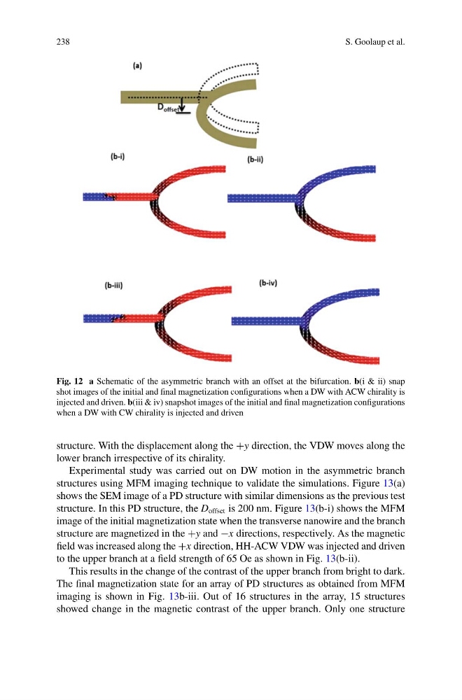
Fig. 12 a Schematic of the asymmetric branch with an offset at the bifurcation. b(i & ii) snap
shot images of the initial and final magnetization configurations when a DW with ACW chirality is
injected and driven. b(iii & iv) snapshot images of the initial and final magnetization configurations
when a DW with CW chirality is injected and driven
structure. With the displacement along the +y direction, the VDW moves along the
lower branch irrespective of its chirality.
Experimental study was carried out on DW motion in the asymmetric branch
structures using MFM imaging technique to validate the simulations. Figure 13(a)
shows the SEM image of a PD structure with similar dimensions as the previous test
structure. In this PD structure, the D offset is 200 nm. Figure 13(b-i) shows the MFM
image of the initial magnetization state when the transverse nanowire and the branch
structure are magnetized in the +y and −x directions, respectively. As the magnetic
field was increased along the +x direction, HH-ACW VDW was injected and driven
to the upper branch at a field strength of 65 Oe as shown in Fig. 13(b-ii).
This results in the change of the contrast of the upper branch from bright to dark.
The final magnetization state for an array of PD structures as obtained from MFM
imaging is shown in Fig. 13b-iii. Out of 16 structures in the array, 15 structures
showed change in the magnetic contrast of the upper branch. Only one structure
S. Goolaup et al.
Fig. 12 a Schematic of the asymmetric branch with an offset at the bifurcation. b(i & ii) snap
shot images of the initial and final magnetization configurations when a DW with ACW chirality is
injected and driven. b(iii & iv) snapshot images of the initial and final magnetization configurations
when a DW with CW chirality is injected and driven
structure. With the displacement along the +y direction, the VDW moves along the
lower branch irrespective of its chirality.
Experimental study was carried out on DW motion in the asymmetric branch
structures using MFM imaging technique to validate the simulations. Figure 13(a)
shows the SEM image of a PD structure with similar dimensions as the previous test
structure. In this PD structure, the D offset is 200 nm. Figure 13(b-i) shows the MFM
image of the initial magnetization state when the transverse nanowire and the branch
structure are magnetized in the +y and −x directions, respectively. As the magnetic
field was increased along the +x direction, HH-ACW VDW was injected and driven
to the upper branch at a field strength of 65 Oe as shown in Fig. 13(b-ii).
This results in the change of the contrast of the upper branch from bright to dark.
The final magnetization state for an array of PD structures as obtained from MFM
imaging is shown in Fig. 13b-iii. Out of 16 structures in the array, 15 structures
showed change in the magnetic contrast of the upper branch. Only one structure