

Domain Wall Programmable Magnetic Logic
231
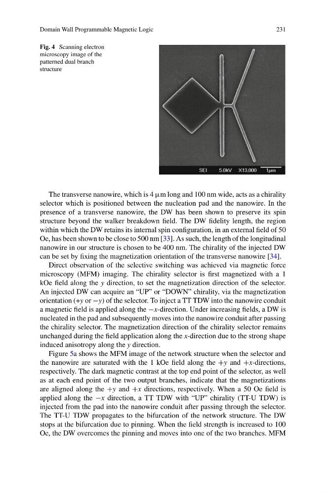
Fig. 4 Scanning electron
microscopy image of the
patterned dual branch
structure
The transverse nanowire, which is 4 μm long and 100 nm wide, acts as a chirality
selector which is positioned between the nucleation pad and the nanowire. In the
presence of a transverse nanowire, the DW has been shown to preserve its spin
structure beyond the walker breakdown field. The DW fidelity length, the region
within which the DW retains its internal spin configuration, in an external field of 50
Oe, has been shown to be close to 500 nm [33]. As such, the length of the longitudinal
nanowire in our structure is chosen to be 400 nm. The chirality of the injected DW
can be set by fixing the magnetization orientation of the transverse nanowire [34].
Direct observation of the selective switching was achieved via magnetic force
microscopy (MFM) imaging. The chirality selector is first magnetized with a 1
kOe field along the y direction, to set the magnetization direction of the selector.
An injected DW can acquire an “UP” or “DOWN” chirality, via the magnetization
orientation (+y or −y) of the selector. To inject a TT TDW into the nanowire conduit
a magnetic field is applied along the −x-direction. Under increasing fields, a DW is
nucleated in the pad and subsequently moves into the nanowire conduit after passing
the chirality selector. The magnetization direction of the chirality selector remains
unchanged during the field application along the x-direction due to the strong shape
induced anisotropy along the y direction.
Figure 5a shows the MFM image of the network structure when the selector and
the nanowire are saturated with the 1 kOe field along the +y and +x-directions,
respectively. The dark magnetic contrast at the top end point of the selector, as well
as at each end point of the two output branches, indicate that the magnetizations
are aligned along the +y and +x directions, respectively. When a 50 Oe field is
applied along the −x direction, a TT TDW with “UP” chirality (TT-U TDW) is
injected from the pad into the nanowire conduit after passing through the selector.
The TT-U TDW propagates to the bifurcation of the network structure. The DW
stops at the bifurcation due to pinning. When the field strength is increased to 100
Oe, the DW overcomes the pinning and moves into one of the two branches. MFM
231
Fig. 4 Scanning electron
microscopy image of the
patterned dual branch
structure
The transverse nanowire, which is 4 μm long and 100 nm wide, acts as a chirality
selector which is positioned between the nucleation pad and the nanowire. In the
presence of a transverse nanowire, the DW has been shown to preserve its spin
structure beyond the walker breakdown field. The DW fidelity length, the region
within which the DW retains its internal spin configuration, in an external field of 50
Oe, has been shown to be close to 500 nm [33]. As such, the length of the longitudinal
nanowire in our structure is chosen to be 400 nm. The chirality of the injected DW
can be set by fixing the magnetization orientation of the transverse nanowire [34].
Direct observation of the selective switching was achieved via magnetic force
microscopy (MFM) imaging. The chirality selector is first magnetized with a 1
kOe field along the y direction, to set the magnetization direction of the selector.
An injected DW can acquire an “UP” or “DOWN” chirality, via the magnetization
orientation (+y or −y) of the selector. To inject a TT TDW into the nanowire conduit
a magnetic field is applied along the −x-direction. Under increasing fields, a DW is
nucleated in the pad and subsequently moves into the nanowire conduit after passing
the chirality selector. The magnetization direction of the chirality selector remains
unchanged during the field application along the x-direction due to the strong shape
induced anisotropy along the y direction.
Figure 5a shows the MFM image of the network structure when the selector and
the nanowire are saturated with the 1 kOe field along the +y and +x-directions,
respectively. The dark magnetic contrast at the top end point of the selector, as well
as at each end point of the two output branches, indicate that the magnetizations
are aligned along the +y and +x directions, respectively. When a 50 Oe field is
applied along the −x direction, a TT TDW with “UP” chirality (TT-U TDW) is
injected from the pad into the nanowire conduit after passing through the selector.
The TT-U TDW propagates to the bifurcation of the network structure. The DW
stops at the bifurcation due to pinning. When the field strength is increased to 100
Oe, the DW overcomes the pinning and moves into one of the two branches. MFM