

232
S. Goolaup et al.
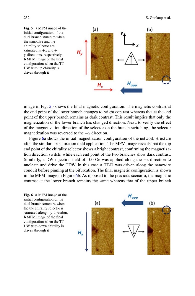
Fig. 5 a MFM image of the
initial configuration of the
dual branch structure when
the nanowire and the
chirality selector are
saturated in +x and +
y-directions, respectively.
b MFM image of the final
configuration when the TT
DW with up chirality is
driven through it
image in Fig. 5b shows the final magnetic configuration. The magnetic contrast at
the end point of the lower branch changes to bright contrast whereas that at the end
point of the upper branch remains as dark contrast. This result implies that only the
magnetization of the lower branch has changed direction. Next, to verify the effect
of the magnetization direction of the selector on the branch switching, the selector
magnetization was reversed to the −y direction.
Figure 6a shows the initial magnetization configuration of the network structure
after the similar +x saturation field application. The MFM image reveals that the top
end point of the chirality selector shows a bright contrast, confirming the magnetization direction switch; while each end point of the two branches show dark contrast.
Similarly, a DW injection field of 100 Oe was applied along the −x-direction to
nucleate and drive the TDW, in this case a TT-D was driven along the nanowire
conduit before pinning at the bifurcation. The final magnetic configuration is shown
in the MFM image in Figure 6b. As opposed to the previous scenario, the magnetic
contrast at the lower branch remains the same whereas that of the upper branch
Fig. 6 a MFM image of the
initial configuration of the
dual branch structure when
the the chirality selector is
saturated along −y-direction.
b MFM image of the final
configuration when the TT
DW with down chirality is
driven through it
S. Goolaup et al.
Fig. 5 a MFM image of the
initial configuration of the
dual branch structure when
the nanowire and the
chirality selector are
saturated in +x and +
y-directions, respectively.
b MFM image of the final
configuration when the TT
DW with up chirality is
driven through it
image in Fig. 5b shows the final magnetic configuration. The magnetic contrast at
the end point of the lower branch changes to bright contrast whereas that at the end
point of the upper branch remains as dark contrast. This result implies that only the
magnetization of the lower branch has changed direction. Next, to verify the effect
of the magnetization direction of the selector on the branch switching, the selector
magnetization was reversed to the −y direction.
Figure 6a shows the initial magnetization configuration of the network structure
after the similar +x saturation field application. The MFM image reveals that the top
end point of the chirality selector shows a bright contrast, confirming the magnetization direction switch; while each end point of the two branches show dark contrast.
Similarly, a DW injection field of 100 Oe was applied along the −x-direction to
nucleate and drive the TDW, in this case a TT-D was driven along the nanowire
conduit before pinning at the bifurcation. The final magnetic configuration is shown
in the MFM image in Figure 6b. As opposed to the previous scenario, the magnetic
contrast at the lower branch remains the same whereas that of the upper branch
Fig. 6 a MFM image of the
initial configuration of the
dual branch structure when
the the chirality selector is
saturated along −y-direction.
b MFM image of the final
configuration when the TT
DW with down chirality is
driven through it