

220
T. T.-H. Kim
in [15], the selected cell is read first followed by write “1”, read “1”, write “0”, and
read “0”. Comparing the counter values can tell the read data. After this, the selected
cell is written with the original read data for restoring.
Then main limitation of the above self-reference sensing technique is requiring
two write operations. Since write operations degrades the MTJ endurance significantly, an advanced sensing technique without destructing cell data is necessary. In
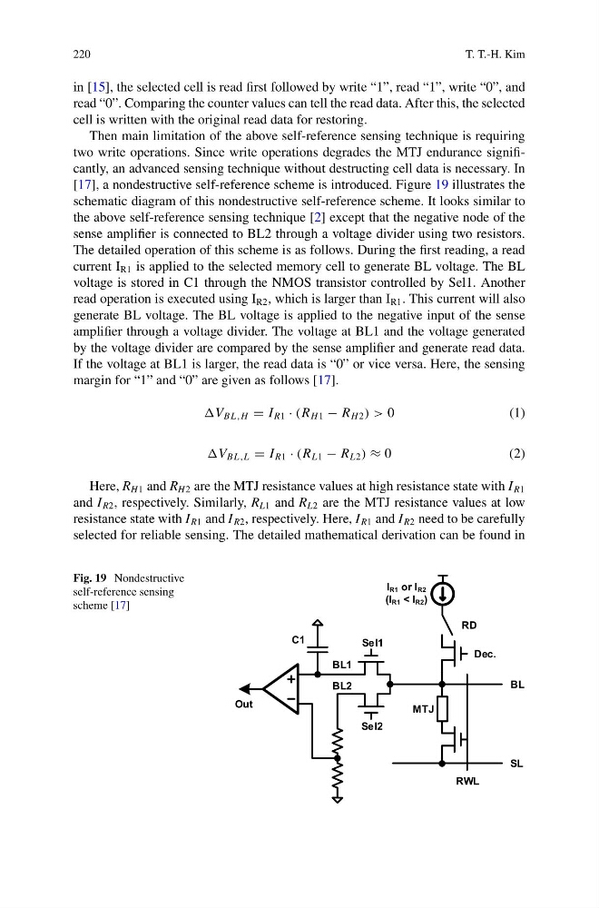
[17], a nondestructive self-reference scheme is introduced. Figure 19 illustrates the
schematic diagram of this nondestructive self-reference scheme. It looks similar to
the above self-reference sensing technique [2] except that the negative node of the
sense amplifier is connected to BL2 through a voltage divider using two resistors.
The detailed operation of this scheme is as follows. During the first reading, a read
current I R1 is applied to the selected memory cell to generate BL voltage. The BL
voltage is stored in C1 through the NMOS transistor controlled by Sel1. Another
read operation is executed using I R2 , which is larger than I R1 . This current will also
generate BL voltage. The BL voltage is applied to the negative input of the sense
amplifier through a voltage divider. The voltage at BL1 and the voltage generated
by the voltage divider are compared by the sense amplifier and generate read data.
If the voltage at BL1 is larger, the read data is “0” or vice versa. Here, the sensing
margin for “1” and “0” are given as follows [17].
B L,H = I R1 · (R H 1 − R H 2 ) > 0
( 1 )
B L,L = I R1 · (R L1 − R L2 ) ≈ 0
( 2 )
Here, R H1 and R H2 are the MTJ resistance values at high resistance state with I R1
and I R2 , respectively. Similarly, R L1 and R L2 are the MTJ resistance values at low
resistance state with I R1 and I R2 , respectively. Here, I R1 and I R2 need to be carefully
selected for reliable sensing. The detailed mathematical derivation can be found in
Fig. 19 Nondestructive
self-reference sensing
scheme [17]
Out
RWL
BL
SL
Dec.
RD
MTJ
I R1 or I R2
(I R1 < I R2 )
Sel1
Sel2
C1
BL1
BL2
T. T.-H. Kim
in [15], the selected cell is read first followed by write “1”, read “1”, write “0”, and
read “0”. Comparing the counter values can tell the read data. After this, the selected
cell is written with the original read data for restoring.
Then main limitation of the above self-reference sensing technique is requiring
two write operations. Since write operations degrades the MTJ endurance significantly, an advanced sensing technique without destructing cell data is necessary. In
[17], a nondestructive self-reference scheme is introduced. Figure 19 illustrates the
schematic diagram of this nondestructive self-reference scheme. It looks similar to
the above self-reference sensing technique [2] except that the negative node of the
sense amplifier is connected to BL2 through a voltage divider using two resistors.
The detailed operation of this scheme is as follows. During the first reading, a read
current I R1 is applied to the selected memory cell to generate BL voltage. The BL
voltage is stored in C1 through the NMOS transistor controlled by Sel1. Another
read operation is executed using I R2 , which is larger than I R1 . This current will also
generate BL voltage. The BL voltage is applied to the negative input of the sense
amplifier through a voltage divider. The voltage at BL1 and the voltage generated
by the voltage divider are compared by the sense amplifier and generate read data.
If the voltage at BL1 is larger, the read data is “0” or vice versa. Here, the sensing
margin for “1” and “0” are given as follows [17].
B L,H = I R1 · (R H 1 − R H 2 ) > 0
( 1 )
B L,L = I R1 · (R L1 − R L2 ) ≈ 0
( 2 )
Here, R H1 and R H2 are the MTJ resistance values at high resistance state with I R1
and I R2 , respectively. Similarly, R L1 and R L2 are the MTJ resistance values at low
resistance state with I R1 and I R2 , respectively. Here, I R1 and I R2 need to be carefully
selected for reliable sensing. The detailed mathematical derivation can be found in
Fig. 19 Nondestructive
self-reference sensing
scheme [17]
Out
RWL
BL
SL
Dec.
RD
MTJ
I R1 or I R2
(I R1 < I R2 )
Sel1
Sel2
C1
BL1
BL2