

Circuit Design for Non-volatile Magnetic Memory
219
WL i
Wl i+1
SL0
BL0
SL ref
V ref
Current Conveyors
SL1
BL1
Differen Amplifier
R hi gh
R low
Ref. Generator
V ref Gen. Unit
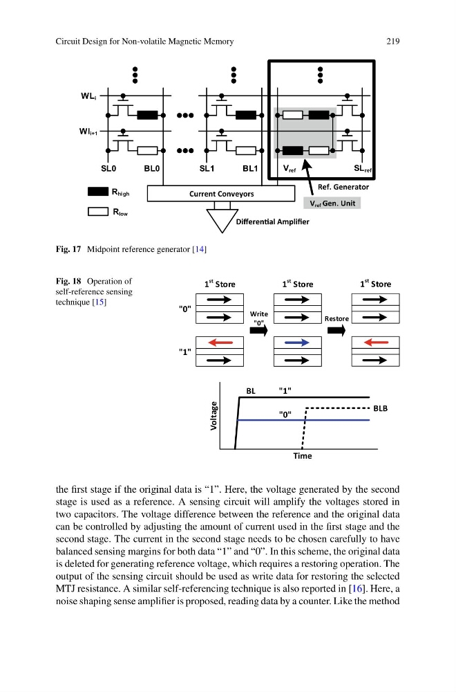
Fig. 17 Midpoint reference generator [14]
Fig. 18 Operation of
self-reference sensing
technique [15]
"0"
"1"
1
st Store
1
st Store
1
st Store
Write
"0"
Restore
BL
"1"
"0"
BLB
Time
Voltage
the first stage if the original data is “1”. Here, the voltage generated by the second
stage is used as a reference. A sensing circuit will amplify the voltages stored in
two capacitors. The voltage difference between the reference and the original data
can be controlled by adjusting the amount of current used in the first stage and the
second stage. The current in the second stage needs to be chosen carefully to have
balanced sensing margins for both data “1” and “0”. In this scheme, the original data
is deleted for generating reference voltage, which requires a restoring operation. The
output of the sensing circuit should be used as write data for restoring the selected
MTJ resistance. A similar self-referencing technique is also reported in [16]. Here, a
noise shaping sense amplifier is proposed, reading data by a counter. Like the method
219
WL i
Wl i+1
SL0
BL0
SL ref
V ref
Current Conveyors
SL1
BL1
Differen Amplifier
R hi gh
R low
Ref. Generator
V ref Gen. Unit
Fig. 17 Midpoint reference generator [14]
Fig. 18 Operation of
self-reference sensing
technique [15]
"0"
"1"
1
st Store
1
st Store
1
st Store
Write
"0"
Restore
BL
"1"
"0"
BLB
Time
Voltage
the first stage if the original data is “1”. Here, the voltage generated by the second
stage is used as a reference. A sensing circuit will amplify the voltages stored in
two capacitors. The voltage difference between the reference and the original data
can be controlled by adjusting the amount of current used in the first stage and the
second stage. The current in the second stage needs to be chosen carefully to have
balanced sensing margins for both data “1” and “0”. In this scheme, the original data
is deleted for generating reference voltage, which requires a restoring operation. The
output of the sensing circuit should be used as write data for restoring the selected
MTJ resistance. A similar self-referencing technique is also reported in [16]. Here, a
noise shaping sense amplifier is proposed, reading data by a counter. Like the method