

Circuit Design for Non-volatile Magnetic Memory
205
lower resistance in both low and high resistance states. But, the high resistance
state is affected more than the low resistance, which leads to a degradation in the
overall TMR ratio as depicted in Fig. 1c. Many materials have also been explored
for enhancing the TMR ratios (Fig. 1c). The TMR ratio is conceptually similar to
on-current to off-current ratios in SRAM or DRAM cells. For reliable sensing, it
is more desirable to have higher TMR ratios. However, in general, the TMR ratios
of magnetic memory are much smaller than the on-current to off-current ratios of
SRAMs or DRAMs. Therefore, reliable sensing in the magnetic memory is very
challenging compared to SRAMs and DRAMs.
3 Magnetic Memory Array Architecture
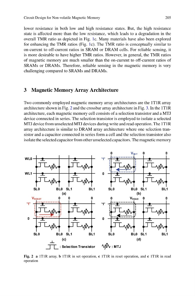
Two commonly employed magnetic memory array architectures are the 1T1R array
architecture shown in Fig. 2 and the crossbar array architecture in Fig. 3. In the 1T1R
architecture, each magnetic memory cell consists of a selection transistor and a MTJ
device connected in series. The selection transistor is employed to isolate a selected
MTJ device from unselected MTJ devices during write and read operation. The 1T1R
array architecture is similar to DRAM array architecture where one selection transistor and a capacitor connected in series form a cell and the selection transistor also
isolate the selected capacitor from other unselected capacitors. The magnetic memory
WL0
WL1
SL0
BL0
'1'
0
0
V SE T
0
0
'1'
0
V RES ET
0
0
0
'1'
0
0
0
0
SL1
BL1
SL0
BL0 SL1
BL1
SL0
BL0 SL1
BL1
SL0
BL0 SL1
BL1
V READ
: Selection Transistor
: MTJ
(a)
(c)
(b)
(d)
Fig. 2 a 1T1R array, b 1T1R in set operation, c 1T1R in reset operation, and c 1T1R in read
operation
205
lower resistance in both low and high resistance states. But, the high resistance
state is affected more than the low resistance, which leads to a degradation in the
overall TMR ratio as depicted in Fig. 1c. Many materials have also been explored
for enhancing the TMR ratios (Fig. 1c). The TMR ratio is conceptually similar to
on-current to off-current ratios in SRAM or DRAM cells. For reliable sensing, it
is more desirable to have higher TMR ratios. However, in general, the TMR ratios
of magnetic memory are much smaller than the on-current to off-current ratios of
SRAMs or DRAMs. Therefore, reliable sensing in the magnetic memory is very
challenging compared to SRAMs and DRAMs.
3 Magnetic Memory Array Architecture
Two commonly employed magnetic memory array architectures are the 1T1R array
architecture shown in Fig. 2 and the crossbar array architecture in Fig. 3. In the 1T1R
architecture, each magnetic memory cell consists of a selection transistor and a MTJ
device connected in series. The selection transistor is employed to isolate a selected
MTJ device from unselected MTJ devices during write and read operation. The 1T1R
array architecture is similar to DRAM array architecture where one selection transistor and a capacitor connected in series form a cell and the selection transistor also
isolate the selected capacitor from other unselected capacitors. The magnetic memory
WL0
WL1
SL0
BL0
'1'
0
0
V SE T
0
0
'1'
0
V RES ET
0
0
0
'1'
0
0
0
0
SL1
BL1
SL0
BL0 SL1
BL1
SL0
BL0 SL1
BL1
SL0
BL0 SL1
BL1
V READ
: Selection Transistor
: MTJ
(a)
(c)
(b)
(d)
Fig. 2 a 1T1R array, b 1T1R in set operation, c 1T1R in reset operation, and c 1T1R in read
operation